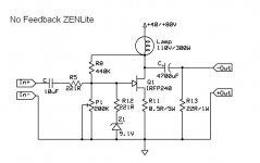
Tyimo said:Do we speak about something like the attached schematic?
Am I understand everyting well? If it is realy working than it is realy an amazing circuit!
That's pretty much it, right there. The 300W 120V lightbulb
is about 30-40 ohms as I recall, and you want to consider a
lesser source impedance for the speaker, which you can achieve
by loading resistance across the output terminal. Try something
like 22 ohms for a start, and consider whether you need an
RC load for baffle step correction. See the article on
www.firstwatt.com
😎
Dozuki said:Going out to my work bench....may actually build up a real one.
I suggest a few ohms, say 100, in series with the Gate to
prevent parasitic oscillation.
You might consider moving R5 to the Gate of the MOSFET, instead of before the bias circuit.
Grey
Grey
Quote from N.P:
Will do.
Is the 9.1V Zener in series with the 221R there to protect the gate only is is there another function? And can you describe what "parasitic" effects may be from just the Zener Alone?
Thanks,
Doug
I suggest a few ohms, say 100, in series with the Gate to
prevent parasitic oscillation.
Will do.
Is the 9.1V Zener in series with the 221R there to protect the gate only is is there another function? And can you describe what "parasitic" effects may be from just the Zener Alone?
Thanks,
Doug
Hi
I would remove the Zener with its series resistor. Should be pretty fine without it. But, the gate must have a resistor. I'd put 220 ohm.
Seems like the most simple circuit ever. Doesn't even need a preamp😀
A real ZEN.

Regards,
Vix
I would remove the Zener with its series resistor. Should be pretty fine without it. But, the gate must have a resistor. I'd put 220 ohm.
Seems like the most simple circuit ever. Doesn't even need a preamp😀
A real ZEN.
Regards,
Vix
Dozuki said:Is the 9.1V Zener in series with the 221R there to protect the gate only is is there another function? And can you describe what "parasitic" effects may be from just the Zener Alone?
As a practical matter, I never let the Gate of the Mosfet see
the outside world except through at least 47 ohms. I also
don't let the outside world see a Zener directly. In these
cases you invite parasitic oscillation, either with the Mosfet or
with the source circuit.
Thanks for the Advice everyone. I will add the 100 Ohms or so the the Gate. As for the 1000 UF Cap, I know it's a little low, But I still get decent Bass, Guess I should see where the roll off really is (and all of my bigger caps are not of very good quality). I believe that I can also use less capacitance on the input, again I will check this (when I dig up the filter formulas... or run some sines throught the amp).
Yea, I think that this is about as simple as it gets. A really striped down Zen. Would also be fun to try building a protype or two that allows one to change out the Fets (including a Pot for Bias) to see what different devices sound like. A bit more complex circuit would probably be benificial as I've found that these circuits are a little easier to stabilize with some Negative Feedback taken off of the input.
And no, it doesn't need a preamp, but it's not going to disturb the neighbors either. A CD player driving it is just about the right level for me when I'm just messin about at the workbench.
Cheers,
Doug
doug
Sorry I have been half sleeping. I think that you have already thought the combination of 220uF and 1000uF for 18dB gain in the range of the frequency bandwidth. Right?
Regards
jH
Sorry I have been half sleeping. I think that you have already thought the combination of 220uF and 1000uF for 18dB gain in the range of the frequency bandwidth. Right?
Regards
jH
Yes, I have 'thought' about it and understand the principle (as far as forming a filter). I have not done any calculations in order to see what would be optimum. The Circuit as it stands was put together on a bread board, and I happened to have a 220UF crossover cap and a 1000 UF cap close at hand with leads that are long enough to easily stick into the breadboard. So, that's what I used to test the circuit. I understand that these form a filter with the bias resistor and the speaker, however, I may be unclear as to what thay have to do with the 18db of gain.
Using 1000 UF on the output I calculate a first order filter with the roll off at about 19 HZ. Ideally this would be a 2200 - 3500 UF cap.
For a highpass of 5 HZ at the input I figgure about .2UF Making a first order filter with the 112K resistor. 100 or so ohms at the gate of the Mosfet shouldn't really affect this.
Please Correct me if I'm Wrong.
-Doug
When selecting values for input vs output rolloff, we greatly
favor the input rolloff frequency as being higher than the output
because you don't want to work the amp harder than you have
to at low frequencies.
It being a current source, the voltage output goes up as the
output cap increases in impedance, and so you want the input
cap to be rolling off first to prevent that.
When selecting values for input vs output rolloff, we greatly
favor the input rolloff frequency as being higher than the output
because you don't want to work the amp harder than you have
to at low frequencies.
Yes, this makes perfect sense. Why have the amp workinging on very low frequencies (which can chew up power) when you are not letting them out of the amp nor going to hear them.
When I posted yesterday with the Cap values, I did make an assumption that the 112K bias resistor is the dominating factor in the input impedance. Did some reading last night and now I feel that this was a wrong assumption.
I admit that I read about Bipolars as I have little written info on Mosfets. But, if this were a Bipolar then the Zin would essentially be Rbe*Beta (with the large values for the bias resistors). However, I'm not sure how to figgure it for a Mosfet.
How would you compute the Zin for this circuit? How would you compute the Zout?
I realize that Zout has little to do with the Output roll off, but since I'm starting to get my head around impeadances in amplifiers it interests me.
...Off to read the original Zen Articles again (read them a few years ago, but could really use the brushing up)
Thanks,
Doug
eLarson said:Aren't R8 and R11 forms of local feedback? (And why both?)
R11 is degenerative feedback (the resistor lowers the
transconductance of the circuit) and R8 gives DC loop feedback
to help stabilize the DC operating point. You want R8 to be
a very high value compared to the source impedance of whatever
drives this circuit in order for R8 to not give significant AC
feedback.
Dozuki said:How would you compute the Zin for this circuit? How would you compute the Zout?
R8 and P1 form the resistive input, keeping in mind that R8
will have an effectively lower value due to the gain of the
amplifier. (Gain = 12 dB means R8 effectively divided by 4)
There is also a capacitive input of the Mosfet Gate. For the
IRF240, Ciss the input capacitance is 1300 pF, and you will
effectively see 1/3 of that, as the Vgs voltage takes up about
1/3 of the input voltage when you have a 1 ohm Source resistor.
The Crss reverse capacitance is 70 pF, which is multiplied by
the gain. In the case of 12 dB, that figure is about 280 pF.
So as a rough estimate you add these together to get
430 + 280 = 710 pF. These figures will vary with Vgs, so if
you really want to know, measure it by observing the bandwidth
with a known source impedance. If the circuit is -3 dB at
200 KHz with a 600 ohm source impedance, your input is about
1.5 nF, if I calculate correctly.
😎
Hmmm....
Even though some will say that this amp does not need a preamp, or a buffer, I still think that buffer should not hurt here. Buffer provides no gain, therefore it should not affect it. It should only provide low output impedance (buffer out=mosfet input). Therefore, why not use it?
I had an idea to employ a tube buffer, with a dual triode, perhaps ECC88. (It should work as a cathode follower, if I am not mistaken) Something like "tube buffered gainclone". But it would be "tube buffered Zen lite" What do you think?
Viktor
- Status
- Not open for further replies.
- Home
- Amplifiers
- Pass Labs
- zen without feedback