you can get matched fets here in the group buy and swap meet section.
whether you need a line driver or not depends on the output current/voltage of the dac you are using and what the input impedance of your next stage is
whether you need a line driver or not depends on the output current/voltage of the dac you are using and what the input impedance of your next stage is
Buffalo II with ZEN I/V
I have built the converter Zen I / V and I have connected to Buffalo II but does not feel too much noise distortion. Wisch modification are needed Zen I / V converter to connect it to Buffalo II that uses a Ess9018.
I have built the converter Zen I / V and I have connected to Buffalo II but does not feel too much noise distortion. Wisch modification are needed Zen I / V converter to connect it to Buffalo II that uses a Ess9018.
daltvi,
Here is a reasonable start. Make sure to add back the filter resistors and capacitors from the article and/or use a quiet supply.
The gain was wrong on this example. Change the 1.5K resistors to 750 ohm, and the voltage supplies to +/-25V and give it a try. You need one set of these for each channel, left and right of a stereo configured 9018.
Looking forward to what you think of the sound.
Cheers,
Dave
Hi..
Im Caad
Sorry to ask in this forum, but has anybody tried to make the IV with Bipolar transistors?
This will lower the input impedance to below 1Ohm.
Im Caad
Sorry to ask in this forum, but has anybody tried to make the IV with Bipolar transistors?
This will lower the input impedance to below 1Ohm.
Hi.
I'm quite intrigued by the designs on this forum. If I have followed correctly, for a PCM1738 (Shanling CDT80 CD) 2.48ma p-p & 2.5v offset, I could use the design of post 261 with the addition of op amps as post 241. I could re-use the original op amps OPA627, the data sheet would seem to advise +/- 5v supply to reduce temperature variations.
A few questions;
1 - the j-fets, do I need grade GR, BL or V?
2 - what would be the (single ended) output level for the 2.48ma input?
I would build one channel initially, then compare L to R before proceeding with the second.
Looking forward to build
This I/V looks good! Simple circuit with good sounding devices and measures well - what could go wrong? 🙂
Input impedance of 15-20 ohms is no problem for most converters. Coupling capacitors are no problem IME... Just look at the schematic of any high-end studio mixer 😉
-Alex
This I/V looks good! Simple circuit with good sounding devices and measures well - what could go wrong? 🙂
Input impedance of 15-20 ohms is no problem for most converters. Coupling capacitors are no problem IME... Just look at the schematic of any high-end studio mixer 😉
-Alex
Last edited:
Buffer added
I´m getting some well matched jfets from Woody (thx man!), so this is what I´ll build... this should be nice!😛
-Alex
I´m getting some well matched jfets from Woody (thx man!), so this is what I´ll build... this should be nice!😛
-Alex
Attachments
Last edited:
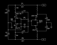
Let´s see... Starting with the schematic above, considering 1mA peak current from AD186x, I select drain resistors of 3.3K and have an output of (3.3K/2)*1m = 1.65V peak = 1.17V rms.
Using matched fets at 10mA idss, the supply rails have to be at least: 15+((3300+221)*10m) = 50.2V.
The drain resistors for the buffer can be 3.3K as well.
R5 will go up to 680K, so the coupling cap can be 0.1 uF. This makes a high-pass at 1/(2*3.1415*680K*0.1u) = 2.34 Hz (-3db).
There´s plenty of places to put LPF. The buffer can be configured as sallen-key LP. This is TBD by measurements and listening.
Looks good?😎
-Alex
Starting with the schematic above, considering 1mA peak current from AD186x, I select drain resistors of 3.3K and have an output of (3.3K/2)*1m = 1.65V peak = 1.17V rms.Using matched fets at 10mA idss, the supply rails have to be at least: 15+((3300+221)*10m) = 50.2V.
The drain resistors for the buffer can be 3.3K as well.
R5 will go up to 680K, so the coupling cap can be 0.1 uF. This makes a high-pass at 1/(2*3.1415*680K*0.1u) = 2.34 Hz (-3db).
There´s plenty of places to put LPF. The buffer can be configured as sallen-key LP. This is TBD by measurements and listening.
Looks good?😎
-Alex
I usually go for a factor of 10, for low thermal noise.
Ans standard CD output is actually 2Vrms, if I am not wrong.
So you should really use 5.6k. Which means even higher power.
Patrick
Ans standard CD output is actually 2Vrms, if I am not wrong.
So you should really use 5.6k. Which means even higher power.
Patrick
Yes, I´m thinking about that. I might use one paralleled AD1865 per channel, as I can do that in my dac. I would have 2mA peak or 4mA peak-peak.😎
As for balanced operation, I´m not interested right now, adds too many parts.
-Alex
As for balanced operation, I´m not interested right now, adds too many parts.
-Alex
Last edited:
Not ok?
Yes, 1mA might be better, since we only have 10mA bias.
Or I might use two fets in parallel. Then the supply would have to go real high.
-Alex
Yes, 1mA might be better, since we only have 10mA bias.
Or I might use two fets in parallel. Then the supply would have to go real high.
-Alex
Last edited:
The first idea was good already, output of 1.17 V rms is ok for me. My speakers are 88 dB sensitive, my inverting LM3886 is set to a gain of 20.
I´ll also change the buffer on my amp to jfet.
-Alex
I´ll also change the buffer on my amp to jfet.
-Alex
Last edited:
This is an idea for the supply, most of it taken from Shunt Regulation Part 2 - diyAudio
Single secondary, lots of R and C, cascode CCS with depletion mode mosfet, and the ground is set by the shunt regs. One supply for both channels.
What do you think Patrick?
-Alex
Single secondary, lots of R and C, cascode CCS with depletion mode mosfet, and the ground is set by the shunt regs. One supply for both channels.
What do you think Patrick?
-Alex
Attachments
With 10mA bias, I would just buy a bunch of 9V batteries, a pair of inductors, and 2 good caps, get the circuit to work, and then worry about the actual power supply later. Maybe you would want to stick to battery in the end.
Patrick
Patrick
Good idea, I might do that for testing.
Discharge tests and capacity measurement of 9 volt transistor radio batteries
-Alex
Discharge tests and capacity measurement of 9 volt transistor radio batteries
-Alex
- Home
- Amplifiers
- Pass Labs
- Zen I/V Converter