Many thanks Joachim.
Please keep us informed of your progress.
BTW if you only need 25mA for the CCS, you might as well use 2xBF862 cascode by 2X J111 or J310 ??
Patrick
Please keep us informed of your progress.
BTW if you only need 25mA for the CCS, you might as well use 2xBF862 cascode by 2X J111 or J310 ??
Patrick
Last edited:
If you use 32 BF245 in parallel then you probably can get to 5 ohm, yes.
So in one single ended SEN you would need 64 BF245s, or 128 for one channel balanced.
And I'd love to see that done.
😉
Patrick
Sorry I saw the low capacitance and thought of a different J-fet. I believe the one that may prove useful for DAC's that are sensitive to input impedance would be the 2sk372V? If we set the goal at 10 ohms input impedance, can you estimate how many 2sk372V in parallel it would require? Also is there a negative to paralleling too many as with tubes, ie 2H goes up?
I guess I've been waiting on reports of the BJT version but seems not much interest. Also I think I have had a subconscious predudice against this project due to not being satisfied with the J-fet version of the Pass D1 that I spent hours and hours and dollars on a couple years ago, ultimately it just wasn't very good. I see now this is a completly different approach.
I have found that low level 60hz (~-100db) can show up with the best non balamced DAC designs, but these floating supplies seem like potentially a great way to reduce the common mode noise.
thanks
Nothing to be sorry about.
The working principle of the circuit is published in Linear Audio and thus in the public domain.
Everyone is welcome to experiment with it as he sees fit.
The performance of the prototypes acts as a guidline as to what can be achieved.
The input impedance equals to the reciprocal of the total transconductance of the upper JFETs in the SEN circuit.
This has been described in the article.
In order to get to below 10 ohms Zin, you would need a total transconductance of 100mS.
The datasheet of 2SK372 says that you will get a transconductance of 60mS at 14mA.
So 2 in parallel should give you 120mS and hence Zin about 8R.
The same applies to any other FETs. No secret, no magic. Just simple maths.
The bipolar version has been built and successfully used by Nikon1975.
We only made those PCBs available to him on request.
So no one else had PCBs from us for the bipolar version.
Patrick
Thanks Patrick, trying my hand at the simulator since i have a bunch of these i'm going for a SEN for my Ess9018 with them.
Ordered some heat-sinks from your site 😎
Ordered some heat-sinks from your site 😎
Finished
Hi Patrick and everyone.
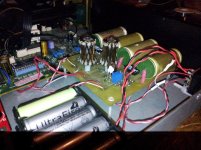
Here is a photo of my finished Cen circuit board complete with mosfet CCS and mobius loop honeycomb IV resistors.
Sounds better than the birds nest Cen i had before, much more refined sound and cleaner highs.
So thanks for sharing your circuit Patrick, much appreciated by all, I'm sure.
Ryan
Hi Patrick and everyone.
Here is a photo of my finished Cen circuit board complete with mosfet CCS and mobius loop honeycomb IV resistors.
Sounds better than the birds nest Cen i had before, much more refined sound and cleaner highs.
So thanks for sharing your circuit Patrick, much appreciated by all, I'm sure.
Ryan
Attachments
Pleasure.
I am sure many here would appreciate a lot if you could post an overall schematics of how you adapt the CEN for the TDA1541.
Best regards,
Patrick
I am sure many here would appreciate a lot if you could post an overall schematics of how you adapt the CEN for the TDA1541.
Best regards,
Patrick
Thank you Patrick,
better to use the 2sk170 (easier to source than 2sk369), can not find the bf862 here in indonesia :-D
Best regards,
Denis
better to use the 2sk170 (easier to source than 2sk369), can not find the bf862 here in indonesia :-D
Best regards,
Denis
Cen with CCS for TDA1541A
Here are my schematics that i used to adapt the TDA1541A with the Cen current conveyor.
I've been able to get the DC offset on the DAC output quite stable (+-3mV max) but im still evaluating its performance and letting the new parts to settle in. The NTC Thermistor compensates for about 2 to 3mV drift from what i can see so far. It may be benificial to use a Thermistor with a higher Beta value, i used 3977K. 4570K may be better, not sure yet.
An externally hosted image should be here but it was not working when we last tested it.
- Home
- Source & Line
- Digital Line Level
- Zen -> Cen -> Sen, evolution of a minimalistic IV Converter