That is not entirely true.
People seem to think that 2SK170 / 2SJ74 or 2SK389 / 2SJ109 are the only ones.
At the F5 thread, I have published curves for 2SK163 / 2SJ44.
They are true complementaries.
I do agree with the differences in capacitances.
But one can handle that in circuit design.
Patrick
People seem to think that 2SK170 / 2SJ74 or 2SK389 / 2SJ109 are the only ones.
At the F5 thread, I have published curves for 2SK163 / 2SJ44.
They are true complementaries.
I do agree with the differences in capacitances.
But one can handle that in circuit design.
Patrick
I like BC550,560, sure. They have high Hfe and this is also very linear over a wide range of idle. They have some early effect though but that is not a problem with common base.
They have high Rbee though of around 130 Ohm. That is not a problem in most I/U converters i think. To lower that you can parallel them in a Faulkner arrangement. The 15mA you chose is also not the null in distortion. That happens when you run each transistor at about 5.5mA. So you could parallel 3 plus 3 BC550,560 each run on 5.5mA.
They have high Rbee though of around 130 Ohm. That is not a problem in most I/U converters i think. To lower that you can parallel them in a Faulkner arrangement. The 15mA you chose is also not the null in distortion. That happens when you run each transistor at about 5.5mA. So you could parallel 3 plus 3 BC550,560 each run on 5.5mA.
> The 15mA you chose is also not the null in distortion. That happens when you run each transistor at about 5.5mA.
I know next to nothing about BJTs.
Could you explain or link to some references ?
Or suggest another BJT for 15mA bias ?
Patrick
I know next to nothing about BJTs.
Could you explain or link to some references ?
Or suggest another BJT for 15mA bias ?
Patrick
> when i follow your link i can not find anything like a circuit schematic.
It links you to post #104 where there is a schematics in spice next to the noise simulation results.
On the left.
Patrick
It links you to post #104 where there is a schematics in spice next to the noise simulation results.
On the left.
Patrick
Hi,
Patrick, I certainly won´t put my veto in for Your circuit in #238. Anybody should feel free to evaluate this not so young circuit. 😉
I do doubt though that it is easy practicable circuit. The double current mirrors are prone to oscillation and need very tight tolerated/matched parts. I´d rather prefer the simple structure with caps, that promises stable working and easier success.
The offset of the bipolar CEN is very low already. It might present a problem with direct coupled MC pickups but not with DACs. The voltage compliance of DACs allows app. +-1V. In BB/TI-DACs this voltage is limited to the Vf of the protection diodes. As long as the voltage swing at the CENs input remain below a couple of dozens of mV there´s no influence on the DACs THD figures.
As Joachim already told, the BCs run well on low idle currents around 5mA. current gain and saturation voltage raise above ~10mA of collector current. For higher currents the Zetex ZTX650, ZTX689, ZTX690 etc. and their complements might be interesting.
jauu
Calvin
Last edited:
That is not entirely true.
People seem to think that 2SK170 / 2SJ74 or 2SK389 / 2SJ109 are the only ones.
At the F5 thread, I have published curves for 2SK163 / 2SJ44.
They are true complementaries.
I do agree with the differences in capacitances.
But one can handle that in circuit design.
Patrick
What/where is the "F5 thread"?
Brad
What/where is the "F5 thread"?
Brad
http://www.diyaudio.com/forums/pass-labs/121228-f5-power-amplifier-869.html#post2277700
EUVL, cancelation of distortion in BJT´s is best when they run on 2/3 Gm theoretically.
That is as far as i remember for third order intermodulation. Other bias conditions can cancel other order distortion so it is a bit complicated. BJT´s in general profit more from degeneration then Fets. When you degenerate Fets too much they develop a complex spectrum. This is different in BJts. See the PDF. This is about BJT´s.
That is as far as i remember for third order intermodulation. Other bias conditions can cancel other order distortion so it is a bit complicated. BJT´s in general profit more from degeneration then Fets. When you degenerate Fets too much they develop a complex spectrum. This is different in BJts. See the PDF. This is about BJT´s.
Attachments
Thanks! It did sound vaguely familiar, but I hadn't been around here for years until running across this thread via Google.
Here is a comparison between Fets and BJTs :
http://www.cco.caltech.edu/~musiclab/feedback-paper-acrobat.pdf
http://www.cco.caltech.edu/~musiclab/feedback-paper-acrobat.pdf
Jawohl! Boyk and Sussman is a great paper, and particularly notable for Boyk allowing that bipolars might not be so bad after all (if you recall, Jim had T shirts made that stated "Digital Finishes What The Transistor Began").
Now to test their simulations with real parts...
Now to test their simulations with real parts...
Each of the 8 differential DACs has an output impedance of about 800 Ohms, but if you use the ESS9018 in stereo mode, like in the Buffalo2, you have about 195 Ohms, and 16mAp-p signal current max riding on top of 8mADC wehn using 0 Ohm load. In mono mode, the ESS9018 has its DACs in parallel giving twice the stereo mode current.
AFAIK, most people are using the ESS9018 in either mono mode or stereo mode.
AFAIK, most people are using the ESS9018 in either mono mode or stereo mode.
Joachim,
The ES9018 has a low output impedance of about 800R.
So let's go as far as we can and aim to do Zin < 1R.
Since it is CEN, the PNP & NPN are in parallel for the signal.
That is why I chose E153 as current source (15mA bias), so that Zin is about 0R8.
This has the same function as your BF245 with trimmer.
E153 are widely used in Japan for powering LEDs.
I am sure Davide would be able to get them if necessary.
I was hoping to get zero DC offset by perfect matching.
Anyhow, the schematics demonstrates how it can fulfill all the functional requirements.
Patrick
bcarso, yes BJTs degenerated to the same Gm as J-Fets have less distortion nominally.
That is mostly because they have much more Gm to burn to begin with. Still some prefer the sound of Fets for other reasons
That is mostly because they have much more Gm to burn to begin with. Still some prefer the sound of Fets for other reasons
> Still some prefer the sound of Fets for other reasons
Absolutely.
If Gm and / or THD is everything then audio would be simple and DIY would be dead boring.
😉
Patrick
Absolutely.
If Gm and / or THD is everything then audio would be simple and DIY would be dead boring.
😉
Patrick
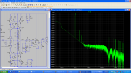
It´s not so much the amount of Gm but the shape of it that is important for low distortion plus the correct topology that takes advantage of the Fets gain curve.
See the simulations on a circuit i designed with only one pair of Fets with EUVLs matching trick and my current mirror with cascode. We got -95dB, mostly 2nd harmonic with a gain of 60dB without any loop feedback.
See the simulations on a circuit i designed with only one pair of Fets with EUVLs matching trick and my current mirror with cascode. We got -95dB, mostly 2nd harmonic with a gain of 60dB without any loop feedback.
Attachments
Here is the datasheet´s information about the ESS9018 analog outputs.
In Stereo mode, you have 4X the currents, and in mono mode, 8X.
50-100mADC idle would be good to have for stereo mode.
In Stereo mode, you have 4X the currents, and in mono mode, 8X.
50-100mADC idle would be good to have for stereo mode.
What is the (current) signal amplitude ?
Patrick
Attachments
Last edited:
The question was to Joachim for what current signal he used in his simulation. (I read 0.1mA.)
Nothing to do with ES9018, the datasheet of which I have under NDA.
Also I wonder how distortion changes with signal amplitude ?
Thanks,
Patrick
Nothing to do with ES9018, the datasheet of which I have under NDA.
Also I wonder how distortion changes with signal amplitude ?
Thanks,
Patrick
One of you sent a email and wanted to purchase a apir of my IV's.
Thank you for your interest.
I do not sell them as finished circuits, but you may wish to consider subscribing for an evaluation kit which will make life somewhat easier for you to build them.
See :
http://www.diyaudio.com/forums/group-buys/196585-sen-cen-all-jfet-iv-converter-evaluation-pack.html
Patrick
- Home
- Source & Line
- Digital Line Level
- Zen -> Cen -> Sen, evolution of a minimalistic IV Converter