Oh, now I see it. DC offset goes to the gates of J2, J3 and J9 and not the drains. My mistake.
About input impedance. You mean 15R rather than 15k right?
I'm sorry I thought you meant output impedance of the DAC circuit being fed into the I-V. The input impedance has been discussed in EUVL's paper as well as this thread.
How would you go about calculating it?
No takers? Here's a hint: http://www.diyaudio.com/forums/pass-labs/140488-b1-turbo-chip.html#post1774444
Now tell me: why did I cascode?
<JAB.R>
Now tell me: why did I cascode?
<JAB.R>
All these were discussed 4 years ago in a lot of details :
http://www.diyaudio.com/forums/digi...minimalistic-iv-converter-28.html#post3393695
The reason why we never bothered to publish is that the cascoded version is prone to oscillations.
So too troublesome for the public.
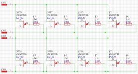
The simplest way to build a SEN today is to use 4~8x 2SK209 in parallel.
Very hard to beat for capacitances, and very tolerant for Vds voltages.
All Idss grades readily available at Digikey.
Just make sure you have gate stoppers for each FET, and thermally couple them.
Patrick
http://www.diyaudio.com/forums/digi...minimalistic-iv-converter-28.html#post3393695
The reason why we never bothered to publish is that the cascoded version is prone to oscillations.
So too troublesome for the public.
The simplest way to build a SEN today is to use 4~8x 2SK209 in parallel.
Very hard to beat for capacitances, and very tolerant for Vds voltages.
All Idss grades readily available at Digikey.
Just make sure you have gate stoppers for each FET, and thermally couple them.
Patrick
Do you find the SW-OPA to be as prone to oscillation? (without gate stoppers on the BF862, and cascoded with J111)
Far enough though, I do have a stoppered version, and turns out this also lends itself to voltage offset correction, so even better.
Not that the 2SK209 isn't also a good option.
Far enough though, I do have a stoppered version, and turns out this also lends itself to voltage offset correction, so even better.
Not that the 2SK209 isn't also a good option.
After having moved my dac was not used for over a year. When I finally got the stereo unpacked again everything seemed to work fine although I thought I heard it clip sometimes. After a while i sometimes lost one phase on one channel. I had Riv and Civ on small perf boards close to the xlr connectors. A track on the perf board was loose causing problem. I then decided to redo the Riv and Civ with a new board and new components (same value for Riv but Civ changed from 300pF Mica to 3300pF styroflex). After that I had distortion on both channels. I thought I made something wrong with Riv and Civ so I removed the perf board and soldered them p2p to the xlr connectors (used new components) but that did not help.
I checked everything and noted that the batteries only gave around 12V (16 AAA), they had been deeply discharged when not used for a long time. I replaced the batteries but the distortion was still there. I then found that the avcc ofbthe buffalo board was oscillating on both channels. A known problem with the version of avcc regulator I have so I solved that by adding caps to the op amp according to instructions found on the twisted pear forum. But the distortion was still there.
I noted that if I reduce the volume in the digital domain in the source (raspberry pi or laptop) the distortion will disappear.
I removed the SEN from the dac and connected the buffalo outputs directly to the xlr connectors via 10uF caps to remove the dc offset and then there is no distortion at all.
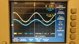
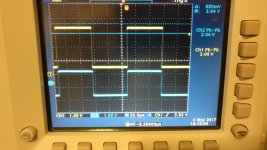
I connected the SEN to a signal generator through a 180 ohm resistor to simulate the output from the es9018 (should be 195 ohm but I did not have any). Vref was connected to 1.6 V to get the offset right. I have attached two photis of the oscilloscope. The first the yellow trace is the output from signal generator and the blue is the output from the SEN after Riv. It looks like the sine wave is distorted in the lower part. I have seen the same when playing a sine wave from the laptop to the SEN via the dac. The second photo shows what happens when I reduce the amplitude of the sine wave. It then looks like the distortion disappears.
I am running out if ideas and would really appreciate some help from you.
I checked everything and noted that the batteries only gave around 12V (16 AAA), they had been deeply discharged when not used for a long time. I replaced the batteries but the distortion was still there. I then found that the avcc ofbthe buffalo board was oscillating on both channels. A known problem with the version of avcc regulator I have so I solved that by adding caps to the op amp according to instructions found on the twisted pear forum. But the distortion was still there.
I noted that if I reduce the volume in the digital domain in the source (raspberry pi or laptop) the distortion will disappear.
I removed the SEN from the dac and connected the buffalo outputs directly to the xlr connectors via 10uF caps to remove the dc offset and then there is no distortion at all.
I connected the SEN to a signal generator through a 180 ohm resistor to simulate the output from the es9018 (should be 195 ohm but I did not have any). Vref was connected to 1.6 V to get the offset right. I have attached two photis of the oscilloscope. The first the yellow trace is the output from signal generator and the blue is the output from the SEN after Riv. It looks like the sine wave is distorted in the lower part. I have seen the same when playing a sine wave from the laptop to the SEN via the dac. The second photo shows what happens when I reduce the amplitude of the sine wave. It then looks like the distortion disappears.
I am running out if ideas and would really appreciate some help from you.
Attachments

How much bias current (> 40mA) ?
Can you measure that between battery and circuit with a multimeter ?
Still the same distortion when you remove the Styroflex ?
Patrick
Can you measure that between battery and circuit with a multimeter ?
Still the same distortion when you remove the Styroflex ?
Patrick
After having moved my dac was not used for over a year. When I finally got the stereo unpacked again everything seemed to work fine although I thought I heard it clip sometimes. After a while i sometimes lost one phase on one channel. I had Riv and Civ on small perf boards close to the xlr connectors. A track on the perf board was loose causing problem. I then decided to redo the Riv and Civ with a new board and new components (same value for Riv but Civ changed from 300pF Mica to 3300pF styroflex). After that I had distortion on both channels. I thought I made something wrong with Riv and Civ so I removed the perf board and soldered them p2p to the xlr connectors (used new components) but that did not help.
I checked everything and noted that the batteries only gave around 12V (16 AAA), they had been deeply discharged when not used for a long time. I replaced the batteries but the distortion was still there. I then found that the avcc ofbthe buffalo board was oscillating on both channels. A known problem with the version of avcc regulator I have so I solved that by adding caps to the op amp according to instructions found on the twisted pear forum. But the distortion was still there.
I noted that if I reduce the volume in the digital domain in the source (raspberry pi or laptop) the distortion will disappear.
I removed the SEN from the dac and connected the buffalo outputs directly to the xlr connectors via 10uF caps to remove the dc offset and then there is no distortion at all.
I connected the SEN to a signal generator through a 180 ohm resistor to simulate the output from the es9018 (should be 195 ohm but I did not have any). Vref was connected to 1.6 V to get the offset right. I have attached two photis of the oscilloscope. The first the yellow trace is the output from signal generator and the blue is the output from the SEN after Riv. It looks like the sine wave is distorted in the lower part. I have seen the same when playing a sine wave from the laptop to the SEN via the dac. The second photo shows what happens when I reduce the amplitude of the sine wave. It then looks like the distortion disappears.
I am running out if ideas and would really appreciate some help from you.
Maybe I am a little dense, but if a change of Civ from 300pF to 3300pF causes distortion, why do you suspect a perf board or power supply??
Jan
Jan/Patrick,
I have the same problem if I remove Civ.
When I could not find an obvious reason for the distortion I decided to check everything I could think of. I did not suspect psu problems as such.
I measured bias on one phase and it was 34mA. I thought it was ok since it is within 2xIdss for V grade 2sk369. I do not remember the idss of my fets but I bought them from Mark. Do you think it is too low? I will measure bias on the rest of them on Monday, left them at work since I have better equipment there.
Many thanks for helping me out
You have a current leakage somewhere in the signal current loop.
This can be caused by leaking caps, or damaged FETs.
34mA is enough, for 10mA signal.
You know the circuit works.
So you just have to trace one at a time.
Patrick
This can be caused by leaking caps, or damaged FETs.
34mA is enough, for 10mA signal.
You know the circuit works.
So you just have to trace one at a time.
Patrick
Did not have much time today but I measured the bias on both phases of one channel to double check and it was 32.6mA on both.
When you say 34mA is good for 10mA signal is that pp or rms?
When you say 34mA is good for 10mA signal is that pp or rms?
I find it a little hard to fully understand the sen circuit. The jfets are biased at Idss and the lower ones are acting as a ccs. So the top jfets needs to conduct more than Idss for negative input currents?
When you say 34mA is good for 10mA signal is that pp or rms?
Correct, just as in a NJFET Source follower.
NJFETs can conduct current > Idss, up to about +0.5V Vgs.
Patrick
NJFETs can conduct current > Idss, up to about +0.5V Vgs.
Patrick
Then I understand the circuit, thanks Patrick.
The 32.6 mA i have measured as bias in my SEN should correspond to Idss of 16.3 mA per 2sk369 which would then be within the range of V grade. But I got the impression that your opinion was that 32.6 mA is too low for the es9018s 18mA p-p output?
The 32.6 mA i have measured as bias in my SEN should correspond to Idss of 16.3 mA per 2sk369 which would then be within the range of V grade. But I got the impression that your opinion was that 32.6 mA is too low for the es9018s 18mA p-p output?
18mA p-p is +/-9mA.
The article said that bias should be 4x that, so in theory 36mA.
But it is not a holy factor.
Patrick
The article said that bias should be 4x that, so in theory 36mA.
But it is not a holy factor.
Patrick
I get it, thanks Patrick.
I recently decided to learn how to design my own PCBs using Kicad. As an exercise i figured it could be fun to make a layout for the 2sk209 version you mentioned would be the first choice today. So I am not sure whether to continue fault tracing the existing SEN or spend the time to make a new 2sk209 version instead. If some of the 2sk369s are broken I will probably not be able to find any replacements anyway.
I recently decided to learn how to design my own PCBs using Kicad. As an exercise i figured it could be fun to make a layout for the 2sk209 version you mentioned would be the first choice today. So I am not sure whether to continue fault tracing the existing SEN or spend the time to make a new 2sk209 version instead. If some of the 2sk369s are broken I will probably not be able to find any replacements anyway.
True
Fault finding is a learning experience which will yield benefits in the future.
Patrick
- Home
- Source & Line
- Digital Line Level
- Zen -> Cen -> Sen, evolution of a minimalistic IV Converter