Why use negative feedback when you get better than -110dB without ?
It is so simple as it is, and yet so high performance.
There are people who tried passive IV of 33R with the PCM1704 with success.
So Zin is not an issue as far as I am concerned.
🙂
Patrick
I've made a few now and the best sounding one so far for PCM1794 was the one with 12 parallel pairs JFETs per half.
Lots of variables changed though so it's hard to say why.
Why use negative feedback when you get better than -110dB without ?
It is so simple as it is, and yet so high performance.
There are people who tried passive IV of 33R with the PCM1704 with success.
So Zin is not an issue as far as I am concerned.
🙂
Patrick
Again, it depends on the DAC and its recommended maximum output voltage swing. Depending on the conversion technique (see the way-back reference about an R-2R approach for an example) one could have non-monotonic behavior, i.e., missing codes.
There are other advantages as well. If the input voltage of the IV is well-determined and very small, offsetting the output of a unipolar DAC is easy, as it only requires a resistor from a low noise voltage source of the appropriate polarity. Also, the noise can be reduced arbitrarily by making the amplifier lower noise. And, by allowing the input common-gate stage to be driven into a forward-biased gate condition even further (while still avoiding any substantial forward gate current) fewer devices are needed; a single 862 or 170 can handle peak drain-source currents of at least 18mA, depending on the Idss to begin with. Also, the use of the amplifier relaxes the requirements on matching of upper and lower JFETs --- the amplifier (which does require a matched pair itself) takes care of the adjustments in the common-gate stage to make the input voltage zero.
The schematic also has a rather attractive look to it in terms of a sort of quasi-symmetry, which I find aesthetically pleasing. One caveat: the compensation may need to be adjusted for specific DACs based on their output capacitance. In this respect the issues are similar to the opamp IV. However, we are dealing with a configuration, the Sen to begin with, which already has a nice low impedance. This helps a lot.
There is also, in the most attractive-looking embodiment, the need for an additional floating voltage source (which need not be especially low noise). However, since the d.c. current involved is negligible (outside of wildly overdriven conditions) this bias voltage can be provided by primary batteries that will last their shelf life, or photovoltaic optocouplers (which I've been testing lately for noise and figuring out how to stabilize against temperature; the Avago parts seem quite suitable).
The approach is also applicable, readily, to the N and P channel complementary input configuration, with some of the same advantages --- except it doesn't solve the "good P-channel" scarcity issue 😀 It does however eliminate the need to pad out the one device to produce a zeroed input voltage, and/or matched complementary transfer functions.
Again, for many DACs the basic Sen or augmented Sen is doubtless just fine. It's just my nature not to leave well enough alone 😀 I wrote in a paper in 1982 while lamenting the excess noise of a photodiode array, which spoiled the anticipated system performance but couldn't be evaluated until the system was completed: "Since some samples of this and other detectors may have lower intrinsic noise, the minimization of extrinsic noise and other errors may have even greater justification..."*
So with continued improvements in DACs, and in other applications besides audio, there may be a practical reason for continued improvements in current conveyors.
Brad
* SPIE Vol. 331, Instrumentation in Astronomy IV (1982)
Last edited:
I've made a few now and the best sounding one so far for PCM1794 was the one with 12 parallel pairs JFETs per half.
Lots of variables changed though so it's hard to say why.
But it at least suggests that lower input Z may be better. Now there may well be some fortuitous mechanism with particular DACs that favors a nonzero input impedance in the IV, for that matter. But it might be sample-dependent.
Again, with feedback we are playing with fire, and I know it's a hot button for many. It can certainly be misapplied. If I were to share some of the speculations I've had about it the moderators would suggest the discussion be moved to the Lounge, if not to journals of abnormal psychology 😱
There is something very nice about the simplicity of the Sen concept, and the ability to readily expand it with paralleled devices, although even SK170 parts can take off and oscillate at VHF with not much provocation. If bias voltages appear to be especially unstable that's something to look for.
If one doesn't mind a little negative feedback, what does look promising, from a consideration of dealing with higher output current DACs especially, is to put the input common-gate device(s) in a tight fast loop. The amplifier involved can be a rather simple topology as it only has to drive one or more JFET gates, and can itself be made out of JFETs. The power supply for the ancillary amp can be referenced to ground, that is, in a conventional non-floating arrangement. The basic Sen core should still use the floating supply.
Simulation results are encouraging, but I haven't built it yet for test and auditioning. BTW this is not the same as the circuit I showed recently in a new thread, using a bipolar Boxall pair as the input device, which was designed to perform a current inversion and offer one approach to differential-to-single-ended conversion, but simply an augmentation of the basic Sen or cascoded Sen.
Brad
So the proposal was Sen-ampstage with globlal NFB. Is this an opamp proposal? I 'm not sure what we debating. NFB won't work feeding to the input of the Sen because the current to voltage conversion hasn't occured unless you are somehow building an discrete opamp with it?
But your proposal reminds me of my favorite I/V prior to the Sen. A simple low resistance passive I/V followed by a Jfet phono preamp type stage which has NFB to itself (after the I/v conversion with the resistor.) So its a low 25-35db local feedback jfet amp for gain to allow the use of a smal passive I/V. Follow it by a nice filter/buffer, works nice.
But the Sen works better because it is simpler, less components, less power supply dependance, etc.
I can't graps how the Sen could be part of a GnFB loop. The Borbely design has that optimized the discrete opamp I/V, but its a high component design and doesn't sound quite as natural as the Sen in my opinion.
A picture (schematic) will be worth a few million words. But I don't want to hijack this thread, so it will be in a separate one. Coming soon. I believe, however, that it combines the considerable and acknowledged benefits of Sen (or Cen) with judicious NFB to address the "input distortion" issues.
It doesn't look like an opamp at all --- there are, for example, no feedback resistors/capacitors whatsoever. Nor is there a "passive" IV conversion ahead of other gain. I've actually already provided some of the elements of the design in my recent inverting current conveyor thread, but this noninverting topology is a good deal simpler, if you don't mind a floating supply like Sen requires. It is also all-NJFET for the "Son of Sen" version.
Being noninverting like Sen or Cen, it is somewhat less versatile for differential-to-single-ended conversion, the latter application being much of the motivation for the inverting design.
How will it sound? My intuition says very good indeed, but time will tell.
Brad
Since you disabled all messages and email to you, would you kindly send me a email via the forum ?
Thanks,
Patrick
Hi Patrick, it's for me? If yes, I don't understood.
Searching for 2sk117, I Just saw the 2sk880 is newly available at mouser, it looks like a smd version of the 2sk117. Is Toshiba renewing its interest in audio JFETs in Smd version ?
It seems widely available, and cheaper than the leaded version. With such low capacitance, it looks like we can parallel more devices. Thinking about buying (and matching) a 3000 pcs reel......
It seems widely available, and cheaper than the leaded version. With such low capacitance, it looks like we can parallel more devices. Thinking about buying (and matching) a 3000 pcs reel......
Searching for 2sk117, I Just saw the 2sk880 is newly available at mouser, it looks like a smd version of the 2sk117. Is Toshiba renewing its interest in audio JFETs in Smd version ?
It seems widely available, and cheaper than the leaded version. With such low capacitance, it looks like we can parallel more devices. Thinking about buying (and matching) a 3000 pcs reel......
Interesting. The datasheet is from 2007, but good on Mouser to carry it. A nice high breakdown voltage too.
When Toshiba discontinued the venerable 2SK389 dual they did have two SMD duals in two package styles that weren't the same chip as the 389, but looked o.k. What I was annoyed by: the package was only 5 pins, with the sources hardwired together 😡 Much less versatile. A six-pin package would have been so easy to do.
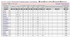
Here are all (15) JFETs left on Toshiba's product catalog.
All SMD, all N-channel, no high Yfs.
Patrick
So the 2145 looks like a dual 880. I note that the spread on transconductance is large, so the 4 mS in the table is probably a little pessimistic. However, it's clear Toshiba isn't making large area parts anymore, and in particular no P channel.
If one is going to consider parts for paralleling and either has low operating voltages in mind, or can cascode, it looks like the NXP BF862 is hard to beat. They do oscillate with little provocation though. Groner shows a circuit in which each has 220nH iirc in series with the gate, which avoids the thermal noise of a resistor.
Interesting. The datasheet is from 2007, but good on Mouser to carry it. A nice high breakdown voltage too.
When Toshiba discontinued the venerable 2SK389 dual they did have two SMD duals in two package styles that weren't the same chip as the 389, but looked o.k. What I was annoyed by: the package was only 5 pins, with the sources hardwired together 😡 Much less versatile. A six-pin package would have been so easy to do.
The LSK389 is still available.
Battery report
I got two six-packs of Ray-O-Vac "Platinum" NiMH AA cells in six-cell holders (they were out of stock on eight-cell ones, which I would have preferred). The open-circuit voltage for one series string of six was about 7.7V. Based on the change in voltage with various loads I deduced that the equivalent series resistance was about 550 milliohms. With excitation from a generator a capacitance term arises that reduces the voltage somewhat at frequencies around a kilohertz. And by around 20kHz the impedance begins to look inductive, of order 3.4uH (surprisingly high I thought). This is the result for one six-pack series string.
As far as noise, it tends to be extremely difficult to see due to magnetic field pickup in any typical lab environment. But by positioning two packs in series carefully, with a battery-powered preamp with a gain of 500 and bandlimiting with simple R-C highpass and lowpass, defining a BW of about 16Hz to 31kHz, I can't reliably see any increase in noise due to the batteries, whether open-circuit or with a 680 ohm load (hence about 22.6mA). The preamp noise referred to the input is about 700pV/root Hz.
One issue with such a battery supply is just getting decent contact to the cells, including the traditional clip and wires. I had to dissect and solder the connections for the clips to get anything sufficiently stable for the measurements.
From these results, admittedly with a very limited sample size, (a) I don't think battery noise is going to be a significant contribution to Sen noise, and (b) I wonder why one doesn't just center-tap the batteries and d.c.-couple to the output resistor. With standard Sen the d.c. offset will be reasonably small with good JFET matching, due to the fairly high output resistance (this accords with the good power supply rejection models earlier). A 1uF film cap across each series half tames (in sim at least) a high well-out-of band resonance, and there appears no need for anything more than that. However, it is slightly less convenient for turning the power supply on and off, since it will be necessary to lift both ends of the battery, and before doing that ground the output, to avoid horrendous transients propagating downstream if the switching isn't done precisely simultaneously.
For cascode-structure Sen the output impedances are very high, making the d.c. offset issue even less of a concern.
Many thanks for publishing your test results. Useful info.
The use of 9V batteries was meant to start people off trying them in the first place.
For real applications I recommended AAA sized NiMH.
These can be obtained with solder tags.
That way you can easily make up a pack with no extra contact resistance of a battery holder.
I also use a simple L-C with highish internal R after the battery.
And the charger circuit I published use a relay to switch between PLAY and CHARGE.
So I think all the above mentioned have been solved ? 🙂
Patrick

Something like this.
Patrick
56 AAA of those is what i'm looking for, not easy to find at a decent price...and genuine.😎
ENELOOP AAA 1Z - Eneloop Micro, AAA, 1Z bei reichelt elektronik
Still cheaper than 4x 10VA R-cores, plus diode, regulators, ........
Patrick
Still cheaper than 4x 10VA R-cores, plus diode, regulators, ........
Patrick
many thanks Patrick,
that's way better price than i had seen up to now ...and half local price.
🙂
that's way better price than i had seen up to now ...and half local price.
🙂
So the proposal was Sen-ampstage with globlal NFB. Is this an opamp proposal? I 'm not sure what we debating. NFB won't work feeding to the input of the Sen because the current to voltage conversion hasn't occured unless you are somehow building an discrete opamp with it?
But your proposal reminds me of my favorite I/V prior to the Sen. A simple low resistance passive I/V followed by a Jfet phono preamp type stage which has NFB to itself (after the I/v conversion with the resistor.) So its a low 25-35db local feedback jfet amp for gain to allow the use of a smal passive I/V. Follow it by a nice filter/buffer, works nice.
But the Sen works better because it is simpler, less components, less power supply dependance, etc.
I can't graps how the Sen could be part of a GnFB loop. The Borbely design has that optimized the discrete opamp I/V, but its a high component design and doesn't sound quite as natural as the Sen in my opinion.
As promised, I've started a new thread with the most basic approach to reducing the distortion at the input of Sen for low source impedances, titled The InSense Current Conveyor. The sim results will be tested with a breadboard soon. It is tempting to jump immediately to a more complex cascoded design, but I'll try to restrain myself. It will also force me to reactivate the Ap, which has been down since a computer crash 🙁
Thanks again to Patrick for stimulating this work.
Brad
- Home
- Source & Line
- Digital Line Level
- Zen -> Cen -> Sen, evolution of a minimalistic IV Converter