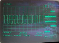
±61KHz
I notice that the square wave takes on very strange shapes at very low frequencies during startup, for a few seconds, until it stabilizes. This only happens if I limit the input current to 3A.
I am attaching a photo of the square wave once the amplifier is working.
I notice that the square wave takes on very strange shapes at very low frequencies during startup, for a few seconds, until it stabilizes. This only happens if I limit the input current to 3A.
I am attaching a photo of the square wave once the amplifier is working.
Attachments
Last edited:
If the FETs were not clamped to the heatsink, would they overheat and fail as they were doing in post #5?
No, after replacing all the driver transistors, they no longer heat up as much as before. Indeed, they reach 30° after about ten minutes without a heat sink. In fact, this morning, to measure the inductances I removed the heatsink again, and now I'm carrying out the tests without it.
Does the amp produce clean audio up to clipping?
Does the board show any discoloration under the inductors?
Does the board show any discoloration under the inductors?
I tested 1Khz and 20Hz at 1V input, and I get a pretty clean output signal. I haven't tested the amplifier at full capacity as I don't think those inductors will last long.
Yes, under the two inductors the board seems to have been heated.
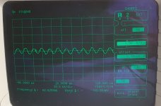
At the output of the two inductances I obtain a rather low value. (Probe 1x)
Yes, under the two inductors the board seems to have been heated.
At the output of the two inductances I obtain a rather low value. (Probe 1x)
Attachments
The 61k idle frequency seems a bit low and could cause undue heating of the inductors. You could try injecting a higher frequency (into the driver board) to see if the idle current drops.
Excess heating for a long period could change the property of the cores which could make them more lossy (less efficient).
Excess heating for a long period could change the property of the cores which could make them more lossy (less efficient).
I hadn't thought of carrying out this test, well, the idle current drops significantly already at 90Khz. At this point I wonder, where could the problem be, in the PWM of the power supply that generates the initial wave?
This is a self-oscillating amp and the frequency is determined by the components at the front-end of the class D circuit. It's possible that one of the small capacitors Check the value of C13 in the diagram you posted.
How much did the current drop?
How much did the current drop?
The current decreased by 3A ±. I removed the small C13 smd capacitor from the driver board and measured it, it measures 1200nF. It should be its correct value.
I don't know if changing the value of the component to increase the frequency is the right solution. Let me explain better, I also thought about increasing the frequency in this way but I also think that if before burning out the output everything worked and absorbed less than 2A at idle, I imagine there is still something to check, probably broken or out of value . Correct me if I'm wrong
That said, I imagine that the ideal working frequency for this output section is around 120KHz, similar to many Korean amplifiers built this way.
That said, I imagine that the ideal working frequency for this output section is around 120KHz, similar to many Korean amplifiers built this way.
I think the inductors are the problem. I think they ran too hot for too long and have changed properties.
Do you have inductors you can swap from a similar amp?
The self-oscillating amps typically drop in frequency at higher power output. This will compound the problem you have now and the low frequency may have caused the inductors to overheat, causing the problem you have now.
Do you know how hot the inductors were running previously?
Mhh no, I don't have any type of similar inductance. Do you think they may have ruined the internal core? I should try to rewind it...
Before they warmed up but not excessively, you could easily hold them in your hand.
Before they warmed up but not excessively, you could easily hold them in your hand.
One reason I hate (HATE) repairing self-oscillating amps is problems like this. Clocked amps have no guesswork.
I think it's operating at too low of a frequency. Other than the 1200pf cap, I don't know what to change to change the frequency. Maybe someone else here could see what a similar amp's idle frequency is.
The thermal damage to the board didn't happen overnight. It takes time.
The first thing I would do (if you aren't going to alter the frequency) is to find inductors that you could drop into the amp. They don't have to be exact. The information I have for a similar amp is that they use 73uH coils. The 68uH should be close enough but not of the cores are bad.
Do you have any inductors that are close to that value (or higher value) that you could install?
At this point I could try changing the value of the capacitor and see how it behaves at a higher frequency. In case I can't, I'll try rewinding the inductors with new wire. Unfortunately I don't have similar inductors.
They don't have to be similar. You don't even have to use the wire that's on them. All you need is for them to be the right value.
Is this your amp?
Is this your amp?
I don't know if it is possible to buy an inductance with the same values. I imagine it holds a lot of current, do you know any sellers who deal in merchandise like this?
The suppliers I know have maximum values of 68uH at max 3A and 73uH at 2A...
The suppliers I know have maximum values of 68uH at max 3A and 73uH at 2A...
You don't buy the inductors pre-made unless the manufacturer (or a clone) will sell them. You buy the cores and the wire and wrap them, after determining what you have with the original.
Do you have a dial caliper?
Do you have a dial caliper?
- Home
- General Interest
- Car Audio
- Zapco SP 2000.1