Yes, exactly, my idea was to look for a seller who had this type of inductance but I couldn't find it. As far as rewinding is concerned, it's not a problem, I have several cores identical to those on these reels, so I only need the wire as this is quite large, and honestly I've never used wire of this diameter. Yes, I have already measured the diameter and I also found a dealer in the area who has it.
Cores are not all the same. They are made of different materials which give them different properties.
I can chime in to share some information I've gotten from working on many zapco sp2000s.
They are simple amps, but quite mangy.
When you have to change the output mosfets and turn on the amplifier without them, you cannot and must not use supply voltages higher than 11 volts, since the rail voltage that is too high, in the absence of the output mosfets, will damage some components on the audio driver board (including 470ohm resistors).
The zapco sp2000 have a design defect that causes NON-polarized capacitors marked CE5 - CE6 - CE12 to fail.
The power supply has almost nothing to do with the audio part.
The correct audio switching frequency is in the order of 110khz and higher if you increase the battery voltage.
The C13 capacitor on the audio driver card must not be 1200"NF" but 1.1NF, in your case, you said you have a 1.2uf capacitor, which is huge, you can confirm that it was a writing error ?
The 2 large inductors, by nature, heat up, especially in this amplifier model, so it's quite normal, even if excessive heating is harmful.
This amplifier model, if powered with little current, is not able to start the oscillation perfectly, so it will tend to absorb all the current you give it (if it were only 6 amps, it will absorb them all), if instead, right from the start, you give it at least 12/15 amperes, the class D stage will be able to turn on correctly, and this will cause the right absorption of the power supply (in my zapco 2000 the right absorption is around 15 Amperes in turn-on for 1 or 2 seconds, then it must settle down to 2.5Ampere).
Check all gate and pulldown resistors of all output mosfets and especially branded low value resistors R46 - R22.
From experience, I usually replace the original transistors on the driver board with FCX690BTA and FCX790ATA, obtaining results identical to the originals, perhaps better.
Yes, I have something salvaged from non-repairable amplifiers for parts, with very similar output section. I would have to look for them because it's not stuff I use often, but I'm sure I've saved them. Unfortunately the winding had been removed as it was damaged, but I was left with the cores, yellow in color (same color as those mounted on the Zapco). I should measure them with a caliper just in case and compare them.Cores are not all the same. They are made of different materials which give them different properties.
Good morning Mario, first of all thank you for this information. As for the supply voltage, good to know, I tested the amplifier several times without mosfets, but every time I used a voltage even lower than 11V. (I increased the voltage only now that the amplifier is complete, to carry out the tests indicated in the previous comments)
Therefore I feel comfortable from that point of view that I did not make a mistake by powering it when the board did not have all the components.
As for the final stage capacitors, I replaced all the electrolytics, and measured the 7 non-polarized ones, obtaining correct measurements.
Regarding the C16 capacitor, thank you for the correction as I would never have noticed otherwise, the correct value is: 1.2nF.
All resistors have been replaced (10Ω and 100KΩ).
The two 2W resistors R22 and R46 are good, measuring 47Ω.
As for the mosfets, I managed to recover a batch of IORs identical to the originals (IRF9640 and IRF640 non-N).
As for the power supply, if I power it without limiting the current (40A maximum), after the initial shock, it stabilizes at 6A±.
I don't understand this anomalous absorption at idle without load...
Mario, are you saying that the audio switching frequency changes with the 12v supply voltage? I don't think I've ever seen that.
I made a mistake, this is not the type of amp that does this thing.Mario, are you saying that the audio switching frequency changes with the 12v supply voltage? I don't think I've ever seen that.
Good morning everyone. The problem has finally been resolved.
Yesterday I built two new inductors with a T130-26 dual toroid core (identical to the original).
The calculations of the relative turns were obtained through the Coil64 calculator.
Having as a starting point the core type (T-130-26) with a permeability of 75, I built the two new inductors using only an 18awg wire and not 6 as in the original, as they would have only served me as tests.
If they had worked I would have rebuilt both with all six wires to increase the current carrying capacity.
After completing them I got two inductors of 76uH and 74uH.
However, after having mounted them, the situation did not change, the amplifier consumed a lot of current when idle and the inductors were as hot as before.
So I reassembled its originals and took a look at the driver circuit again.
Having changed all three ICs, I began to doubt that there was something faulty, and in fact, tl072 was probably faulty (installed new a few days before).
After replacing it with a new one, the amplifier works properly again.
Its idle current dropped to 2.59A at 14V and the frequency stabilized at 130kHz.
Thanks to everyone who helped me understand more about it.
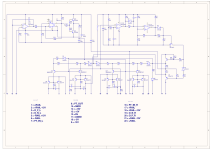
I attach .rar package with the diagram of the DWG1216 board reconstructed starting from the diagram posted at the beginning of the thread. I corrected the values of some components, replaced the BCXs with the transistors that this amplifier uses as standard and corrected two transistors that were incorrectly upside down in that diagram I found on the internet.
Furthermore, I am also attaching the Altium file to be able to modify it in case of errors. (There probably will be some)
VirusTotal Scan of .rar
Yesterday I built two new inductors with a T130-26 dual toroid core (identical to the original).
The calculations of the relative turns were obtained through the Coil64 calculator.
Having as a starting point the core type (T-130-26) with a permeability of 75, I built the two new inductors using only an 18awg wire and not 6 as in the original, as they would have only served me as tests.
If they had worked I would have rebuilt both with all six wires to increase the current carrying capacity.
After completing them I got two inductors of 76uH and 74uH.
However, after having mounted them, the situation did not change, the amplifier consumed a lot of current when idle and the inductors were as hot as before.
So I reassembled its originals and took a look at the driver circuit again.
Having changed all three ICs, I began to doubt that there was something faulty, and in fact, tl072 was probably faulty (installed new a few days before).
After replacing it with a new one, the amplifier works properly again.
Its idle current dropped to 2.59A at 14V and the frequency stabilized at 130kHz.
Thanks to everyone who helped me understand more about it.
I attach .rar package with the diagram of the DWG1216 board reconstructed starting from the diagram posted at the beginning of the thread. I corrected the values of some components, replaced the BCXs with the transistors that this amplifier uses as standard and corrected two transistors that were incorrectly upside down in that diagram I found on the internet.
Furthermore, I am also attaching the Altium file to be able to modify it in case of errors. (There probably will be some)
VirusTotal Scan of .rar
Attachments
Did the working TL072 come from the same batch as the one that was operating at the low frequency?
Are the now-working inductors using the same exact cores that were originally in the amp and the same number of turns as the original inductors?
Are the now-working inductors using the same exact cores that were originally in the amp and the same number of turns as the original inductors?
They are from the same manufacturer but were not purchased from the same seller.
As for the inductors, the original ones are present again as they were not damaged but the drop in frequency was due to the integrated circuit.
However, as regards the test inductors (which worked after having mounted the new integrated chip) I used 4 T130-26 cores with 3 yellow faces and one white, identical to the originals. I stacked two(one on top of the other like the originals) and wrapped the wire. The calculator calculated 20.8 turns of thread needed. The original coils have 20 + one external turn that goes around from the top and ends on the other side. This is how I created the two new inductors used for the test.
Last edited:
- Home
- General Interest
- Car Audio
- Zapco SP 2000.1