Another mod - this is the op-amp regulator mod, which I'll call mod3.
The main purpose of this mod is to simplify the +12v/-12v voltage regulators for the opamps, which are a pair of 7812/7912 3-terminal regulators on the Yuanjing board. That's fine, but their reference ground is bang in the middle of the section of ground plane between the large PSU filter caps and the small electrolytics for the LM3886. That section of ground plane is also contaminated by speaker return-currents. The output bypass caps for the 7812 and 7912 are also grounded in the plane where the speaker return-currents flow back.
I considered isolating the ground pads for the 7812/7912 and jumpering them to a star ground near the PSU power connector, but that doesn't solve the problem of the grounding of the bypass caps. So the solution I'm adopting is to replace the 7812 and 7912 and their output bypass caps with a simple 12v zener shunt regulator for each rail, with the zero reference for each zener being the ground of the power connector.
1) Remove the 7812 and 7812, as well as their output bypass caps (100 uF and 100 nF on each rail near the 7812/7912).
2) Jumper the input of the 7812 to its output, and similarly for the 7912. There's a 470 ohm/0.5W resistor from each rail to the input of each regulator - leave these intact. These will be the current limiters for the zener shunt regulators
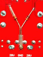
3) Solder a 12V, 1W zener on the solder-side of the PCB as shown in the picture below for each rail of the opamps - take care with the polarity of each zener. The ground for each zener is referenced directly from the ground of the power connector.
After this mod, the +12v/-12v rails to the opamps are not regulated as tightly as before, but the ground-bounce component in each rail will be greatly reduced, since they're isolated from the speaker return-current paths.
I'll try to give my subjective impressions of the improvement in audible sonics (if any) due to this mod in a later post.
Caution: If you perform this mod, measure the voltages on the +12v/-12v rails for the op-amps with the op-amps removed from their sockets. If there's an error in doing the mod, there's every possibility of an over-voltage that will let out the magic smoke from the op-amps - which will be tragic if they're high-end LM4562 or THS4032 op-amps. It pays to check everything before plugging in the op-amps.
The main purpose of this mod is to simplify the +12v/-12v voltage regulators for the opamps, which are a pair of 7812/7912 3-terminal regulators on the Yuanjing board. That's fine, but their reference ground is bang in the middle of the section of ground plane between the large PSU filter caps and the small electrolytics for the LM3886. That section of ground plane is also contaminated by speaker return-currents. The output bypass caps for the 7812 and 7912 are also grounded in the plane where the speaker return-currents flow back.
I considered isolating the ground pads for the 7812/7912 and jumpering them to a star ground near the PSU power connector, but that doesn't solve the problem of the grounding of the bypass caps. So the solution I'm adopting is to replace the 7812 and 7912 and their output bypass caps with a simple 12v zener shunt regulator for each rail, with the zero reference for each zener being the ground of the power connector.
1) Remove the 7812 and 7812, as well as their output bypass caps (100 uF and 100 nF on each rail near the 7812/7912).
2) Jumper the input of the 7812 to its output, and similarly for the 7912. There's a 470 ohm/0.5W resistor from each rail to the input of each regulator - leave these intact. These will be the current limiters for the zener shunt regulators
3) Solder a 12V, 1W zener on the solder-side of the PCB as shown in the picture below for each rail of the opamps - take care with the polarity of each zener. The ground for each zener is referenced directly from the ground of the power connector.
After this mod, the +12v/-12v rails to the opamps are not regulated as tightly as before, but the ground-bounce component in each rail will be greatly reduced, since they're isolated from the speaker return-current paths.
I'll try to give my subjective impressions of the improvement in audible sonics (if any) due to this mod in a later post.
Caution: If you perform this mod, measure the voltages on the +12v/-12v rails for the op-amps with the op-amps removed from their sockets. If there's an error in doing the mod, there's every possibility of an over-voltage that will let out the magic smoke from the op-amps - which will be tragic if they're high-end LM4562 or THS4032 op-amps. It pays to check everything before plugging in the op-amps.
Attachments
Last edited:
OK - the first subjective impressions are that there's no regression in audible sonics with a zener shunt regulator and LT1213 opamps. There's probably less background hash and more detail in the highs, but this is fairly subtle.
The good news is that it's no worse than before, and there's a reduction in the BoM - 2 regulators, 2 electrolytics and 2 small film caps have been removed, and 2 1W, 12V zeners have been added.
Edit: The 470 ohm, 0.5W resistors get hot to the touch - maybe 60-65 Celcius. I'll upgrade them to 470 ohm, 1W later.
Last edited:
Could I ask you to build me a chip amp.
Hey linuxguru,
I cannot understand most of your posts. But, well, could I ask you to build me a chip amp sometime ?
I just ebayed a tube buffer pre amp + lm3886. If I like it, I'd probably want to build a audiophile grade 7.3 amp.
Now that could be clean over my head. So I thought I'd enlist someone.
Thanks in advance.
Cool.
Srinath.
the problem we are having comes from the universal use of the same symbol for Ground in all these schematic drawing software packages.
Yes, that and the legions of PCB designers who've only designed digital circuit boards (PC motherboards, PCI cards, ...). To a digital circuit designer, a ground plane is perfectly natural, and connecting the grounded end of any component to the ground plane is the default choice.
To be sure, there are very large currents near the VRM and CPU socket, but those layouts have all been standardized by the processor manufacturers. There's no thinking involved, just bypass Vcore to Vss like crazy with zillions of MLCCs. Sprinkle in a few electrolytics near the VRM, and it's done...
Everything is correct, except the value of R3 in your drawing. It stays the same as before - 680 ohms in your drawing (1k on the Yuanjing board), not 10 ohms as you have shown (which would make the gain of the LM3886 too high).
With 10 ohms at R3, the closed-loop gain of the LM3886 would be ~2200, which would drive it into clipping with signal levels as low as 10s of mVs. 680 ohms to 2.2k is a reasonable range of values for R3.
Ok, at least my stupidity has a excuse. My board has 10ohm resistors on it, and I tried to follow instructions directly and never changed them. I'm out of town for a week, but I'll try it again when I return. THANKS AGAIN!!!
Another op-amp worth trying: The JFET-input LT1057. It's a hard call between the sonics of the LT1213 and LT1057. My preliminary impressions are that the LT1213 has more detail, but the LT1057 is more full-bodied, warmer and less fatiguing. I'll see how it goes...
Not so Soft start
HI
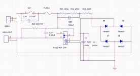
i have installed a soft start board but i still get a turn on thump! the volts appear at the out as soon as swicth on and the relay clicks a second later.I think i have installed components correctly.wiring is straight forward ,switch and volts in and out .i am expecting something from this board doesnt provide ie no thump?could a component be wrong?
any thought please!
HI
i have installed a soft start board but i still get a turn on thump! the volts appear at the out as soon as swicth on and the relay clicks a second later.I think i have installed components correctly.wiring is straight forward ,switch and volts in and out .i am expecting something from this board doesnt provide ie no thump?could a component be wrong?
any thought please!
Attachments
Is this for the Yuanjing? I have no idea about using a soft-start relay - but I get a small turn-on thump on my Jim's audio board with a 10k mute resistor and 120 uF mute cap. You may want to increase the mute cap to 150, 220 or 330 uF.
HI yea its for my Yuenjing (linuxguruModB!).i intended it for later multiamp/transformer project.guy from jims audio says it isnt designed to stop thump specifically but for high power amp switch on surge.
where are these mute components you mentioned placed?
where are these mute components you mentioned placed?
I was hoping the softstart would reduce thump so i wouldnt need multiple speaker protection circuits in my triamp project.
Oh yea ive just won a speaker protection kit for $7!! so a guess, if you'll pardon the pun ,its a MUTE point!haha
Oh yea ive just won a speaker protection kit for $7!! so a guess, if you'll pardon the pun ,its a MUTE point!haha
where are these mute components you mentioned placed?
On the Jim's audio board, next to the LM3886 on each side near the edge of the PCB. They're between the speaker connector and the heatsink. There's one (~100 uF) electrolytic and a 10k resistor.
things seem to have gone downhill slightly!while i was modding i have been using ipod as source (mini jack soldered to inputs) now i plug in dvd player (phono to phono) ive got hum .if i disconnect signal ground that goes only leaving hum with volume turned up.now im wondering if mods wernt right adn the ipod connection somehow masked this!!
It's a ground loop for sure, if disconnecting a signal ground reduces hum. Check the chassis ground and see if it's isolated from the power ground, or at most a single point connection to the power ground.
Vaguely related - the Goldmund/Symasym kit is back on EBay:
High speed power amplifier w/spk protection Goldmund ! - eBay (item 320510427890 end time Apr-30-10 08:32:56 PDT)
This is the less expensive ($42.99) kit without the output BJTs and main PSU caps.
High speed power amplifier w/spk protection Goldmund ! - eBay (item 320510427890 end time Apr-30-10 08:32:56 PDT)
This is the less expensive ($42.99) kit without the output BJTs and main PSU caps.
I only hve one chassis ground with the earth from mains and 0v connected to it.removing the 0v wire made no difference.putting the signal wire into the original pcb connectors works (only leaving hum at high volume) so maybe my lifted ground mod is in error.
also as you say maybe the pcb for improved version may come up for sale and i can transfer my components!
also as you say maybe the pcb for improved version may come up for sale and i can transfer my components!
Finally tried the LME49860 (aka LM4562) in the Jim's Audio/Yuanjing board - it's audibly the best balanced of all the op-amps I've tried so far. There are some tracks that are more musical on the LT1057 or LT1213, but the LM4562 has the least coloration and the most consistent sonics across the board. Highs and upper-mids may be a bit bright for some, but for me it's a keeper - the detail in the strings and vocals is simply brilliant...
Im happy with mine with burrbrown opa2134's.
Oh i was being a bit dense early and i dont get much speaker thump only when swithcing on/off after short intervals!
Oh i was being a bit dense early and i dont get much speaker thump only when swithcing on/off after short intervals!
I agree, the LM4562 is the best I could find at a sensible price. I have found another case. RadioSpares RS 665-7719. It's a 2U black rack type case complete with handles for £43-75p. I'm going to order one for the Goldmund. Iv'e got all the other bits now, so should complete it in a few weeks. Then if I prefer it to the Yuanjing I shall try to sell that one on ebay.
I just began assembling the Symasym/Goldmund. Depending on how it sounds, either the Goldmund or one of the Yuanjings will probably go into a vintage Technics SU-8011 that I picked up recently. The Technics is partially functional, with good PSU, switches, connectors, pots, etc. - but only one good channel. It is a good candidate for implanting a Gainclone or the Symasym/Goldmund, since it has ample space inside. The rails are ~ +/- 34 V, which is just about right for LM3886 as well as the Symasym/Goldmund.
Regarding the 2 x 79 pF silver micas in the Goldmund kit, they are mounted at the locations labelled 49 pF on the PCB. This value is still a bit low - Symasym uses 330pF to ground at this location. If you find the Goldmund to be unstable, it might help to go for a higher value than 79 pF here.
My Goldmund kit came with 3.01 ohm, 0.5W resistors for the Boucherot Cells. IMHO, that value is a bit low and might hurt sonics. 10 ohm, 1W is a more suitable value - I'm using the 3 ohms for the first pass, but may opt for 10 ohms on a future tweak.
I'm also considering upgrading the rail caps for the input and VAS sections to 220 or 330 uF, rather than the supplied 100 uF. The main PSU filter caps are Panasonic TS-UP 22,000 uF / 50V, which are surprisingly compact.
In the Goldmund kit, there are two additional tiny axial lead devices with resistor-like colour codes, but do not measure as resistances - their DC resistance is infinity. They're about the same size as 1/8 W resistors. Are these the 100 pF ceramic RF-suppression caps to be installed from gate to ground at the input?
- Status
- Not open for further replies.
- Home
- Amplifiers
- Chip Amps
- "Yuanjing" Gainclone 3886 - eBay amazing value ?