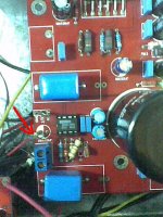
thanks 🙂I can't take photos right now, but this image shows what is done on the reverse side of the board.
So, my modification is correct?


Ground-lift resistor (10 ohm, 1W) is mounted vertically in GND hole a cap or no?
Hi, now I see that your board is different from mine, I have jim's audio board. There is some difference in components rotation, but it's very similar.
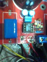
Your wires seems to be correct, in the plus side of the capacitors.
But, your 10ohm 1W resistors are in wrong position, it must be reverted, the exposed wire should be in plus side of the place where were the capacitor, which is the place you will solder the IN GND wire.
See the pictures. (sorry for the bad vga quality)
Attachments
The plan is to power my 10-drivers OB using multi-channel gainclone. Was ready to build the usual point-to-point 3875 until I spotted this on EBay.
An externally hosted image should be here but it was not working when we last tested it.
Price is amazing, which comes to about A$12/channel (!). Very tidy. What I am not sure though is the additional op-amp which I believe can be easily bypassed. The other thing, I haven't heard 3888 compared to 3875. I have lived with my 3875 and never had the need to tweak or lust any other amp since day-1.
Any advise?
man, i dont recommend you to try this too since i tried a 1875 before, it played sucked, but after rebuild with the same ICs off the board, it sounded OK, so that's it.
The plan is to power my 10-drivers OB using multi-channel gainclone. Was ready to build the usual point-to-point 3875 until I spotted this on EBay.
An externally hosted image should be here but it was not working when we last tested it.
Price is amazing, which comes to about A$12/channel (!). Very tidy. What I am not sure though is the additional op-amp which I believe can be easily bypassed. The other thing, I haven't heard 3888 compared to 3875. I have lived with my 3875 and never had the need to tweak or lust any other amp since day-1.
Any advise?
I suggest you replace the above filter capacitor. Because they are fake.
Genuine skin capacitance is different.
In China, no one to buy yuanjing products because they use a lot of old, and fake parts.
I just came across one of these LM3886/NE5532 boards. Does anyone have a schematic for these? On regarding a mod of these boards, what is stopping us from making these a Hovland current pump similar to the MyRefC?
The yellow ones are unlikely to be rated X2.
They are probably MKT or MKS in 50V or 63V rating.
They are probably MKT or MKS in 50V or 63V rating.
In China, no one to buy yuanjing products because they use a lot of old, and fake parts.
And what do they buy?
It would be interesting to know what are considered good for the people there.
Just one correction: old and fake are not necessarily synonymous. A 5532 chip is an old design and many people or products are still using it. A Wima capacitor can be old but it's still very good. Both products can be improved, but they are good.
Old design and an old part are two different things. A old design might be good, an old chip might work too.
I think what he is implying with "Old and Fake" is "Dried up electrolytic cap re-badged to sell to gullible Amuricans who want to see Rubycon stamped on it."
I think what he is implying with "Old and Fake" is "Dried up electrolytic cap re-badged to sell to gullible Amuricans who want to see Rubycon stamped on it."
AndrewT
Am I incorrect in thinking the NE5532 could duplicate the function of the LM318 on the MyRefC and make these Yuanjing boards similar to the MyRefC?
Am I incorrect in thinking the NE5532 could duplicate the function of the LM318 on the MyRefC and make these Yuanjing boards similar to the MyRefC?
You are incorrect, yes, in assuming a 5532 or any other chip will behave exactly as the LM318 on the MyRefC.
Many people tried different chips on the MyRefC and it didn't work as it did with the 318.
Consider this chip as if it was the LM3886. You wouldn't change that chip on the MyRefC, would you?
Many people tried different chips on the MyRefC and it didn't work as it did with the 318.
Consider this chip as if it was the LM3886. You wouldn't change that chip on the MyRefC, would you?
carlmart
Thanks for the reply. I don't have a schematic for these boards so I don't know how they are designed to work but the layout looked similar to the MyRefC to me so I imagined they might be modded to work as a current pump like the MyRefC. Do you know the purpose of NE5532 on these boards?
Thanks for the reply. I don't have a schematic for these boards so I don't know how they are designed to work but the layout looked similar to the MyRefC to me so I imagined they might be modded to work as a current pump like the MyRefC. Do you know the purpose of NE5532 on these boards?
To start with the 5532 couldn't be replacing an LM318, because the 5532 is a dual chip and the 318 is single.
So that might be the case for a "weird" MyRefC if they were using both sides of the 5532 to feed both channels. But no, they are using two 5532 on the eBay kit.
Second the number of parts is much less than in a MyRefC. I have one, from the old Penasa layout, and it has much more parts than this kit seems to have.
Without seeing the Yuanjing schematic I can only guess what the 5532 is doing, like being a buffer and line amp, or a line amp and a DC servo for the whole amp.
Isn't it possible to get the original schemartic?
carlmart
I suppose someone like linuxguru might draw the circuit from the traces but I looked and couldn't find any schematic. Having many more parts and two dual op-amps feeding the LM3886's doesn't seem to eliminate the possibility of the yuanjing working like a Howland current pump. The reduced part count also does not automatically eliminate the possibility of that suggested mod. The NE5532 can be just as quiet as the LM318 and probably quieter if handled correctly so the question is whether the four nodes on the two NE5532's can make the LM3886 meet the constant current requirement. I suspect it should be able to very well, providing the circuit board doesn't make it too difficult. Mauro is a very competent designer and I suspect that he could have chosen the NE5532 if he thought it was better but he may have been more comfortable with the LM318 quirks or more familiar with the Musical Fidelity circuit which inspired the MyRefC and based his decision for the part on the easiest route to success.
I suppose someone like linuxguru might draw the circuit from the traces but I looked and couldn't find any schematic. Having many more parts and two dual op-amps feeding the LM3886's doesn't seem to eliminate the possibility of the yuanjing working like a Howland current pump. The reduced part count also does not automatically eliminate the possibility of that suggested mod. The NE5532 can be just as quiet as the LM318 and probably quieter if handled correctly so the question is whether the four nodes on the two NE5532's can make the LM3886 meet the constant current requirement. I suspect it should be able to very well, providing the circuit board doesn't make it too difficult. Mauro is a very competent designer and I suspect that he could have chosen the NE5532 if he thought it was better but he may have been more comfortable with the LM318 quirks or more familiar with the Musical Fidelity circuit which inspired the MyRefC and based his decision for the part on the easiest route to success.
I seriously doubt anyone, with the images provided, can back-engineer this circuit. Did you ask the seller if they can't provide one?
Perhaps you should find out more on people that did try other ICs instead of the 318. The question is slew-rate speed, no noise, and bandwidth that makes the 318 unique for this application.
Why would anyone pick a 5532 instead of a single chip, even the 5534, to design a commercial product that supposedly clones a proven design?
I don't think picking the 318 was because it made Mauro feel better or familiar with it. In fact many said the original MF amp was not really a Hovland current pump.
My opinion: this amp is not a MyRefC clone. I don't think it deserves any more discussion, at least for me.
Being cheap enough, if you're curious you should buy it. It's a cheap bet, and you can still use the amp.
carlmart
I never said that the yuanjing in this thread was a MyRefC clone, only that it might be modded to imitate its function. The NE5532 can be made to perform very quietly with slew rates and bandwidth comparable to the LM318 as I understand it and if the LM3886 is doing the heavy lifting, it could conceivably make a very good Howland. What would be the purpose of using two NE5532 chips to drive one pair of LM3886 chips if not to create a high impedence current source? I just ordered two of these boards and hope to provide more information after I get them. For the record, I believe linuxguru also owns these boards.
I never said that the yuanjing in this thread was a MyRefC clone, only that it might be modded to imitate its function. The NE5532 can be made to perform very quietly with slew rates and bandwidth comparable to the LM318 as I understand it and if the LM3886 is doing the heavy lifting, it could conceivably make a very good Howland. What would be the purpose of using two NE5532 chips to drive one pair of LM3886 chips if not to create a high impedence current source? I just ordered two of these boards and hope to provide more information after I get them. For the record, I believe linuxguru also owns these boards.
carlmart
I suppose someone like linuxguru might draw the circuit from the traces but I looked and couldn't find any schematic.
The NE5532(s) on the Yuanjing gainclone are simple voltage gain and buffer stages, and are not nested around the LM3886, unlike the MyRef. Apart from that, the Yuanjing has various layout and grounding issues that make it fairly rough-sounding. You can use it as an inexpensive HT component, but not for any serious audiophile 2-channel application.
The MyRef Rev C (and later variants like the Rev E/FE) are way superior to the Yuanjing in imaging, soundstage, definition, micro-detail and distortion. If you're interested, PM me for details on bare MyRef PCBs and kits that I offer.
linuxguru
Nice to see your reply. I already own the ultimate BOM and original versions of the MyRefC so my interest is not in trying to cheaply clone a MyRefC but in the academic exercise of exploring its current sourcing function. I have noted that there were at least two versions of these yuanjing boards, do the latest ones have the same ground plane issues? What might we need to mod the latest board so that one of the NE5532 op-amps handle the voltage gain while the other creates the high impedence current source with the LM3886? By the way, if you have the circuit for the yuanjing, please post it or mail it to me.
Nice to see your reply. I already own the ultimate BOM and original versions of the MyRefC so my interest is not in trying to cheaply clone a MyRefC but in the academic exercise of exploring its current sourcing function. I have noted that there were at least two versions of these yuanjing boards, do the latest ones have the same ground plane issues? What might we need to mod the latest board so that one of the NE5532 op-amps handle the voltage gain while the other creates the high impedence current source with the LM3886? By the way, if you have the circuit for the yuanjing, please post it or mail it to me.
So for the potentiometer connections...
Which holes are what because I just killed two potentiometers because they overheated from me hooking them up the wrong way. Now they are all scratchy...
http://www.bitechnologies.com/pdfs/p231.pdf
I'm using two of these pots.
If you look at the little diagram...I know I'm being a pain in the butt, but could someone tell me where each connection on the board goes to. (Which terminal). CCW goes to ground? CW to out? S to In?
Is that right?
Thanks.
Connecting a potentiometer the wrong way won't harm it, It will just not work right.
Scratching comes from not having a capacitor between pot wiper and amp input.
CCW to ground, S to amp, CW to signal source.
Scratching comes from not having a capacitor between pot wiper and amp input.
CCW to ground, S to amp, CW to signal source.
yeah well whatever it is. they got messed up. they did get really hot once and nothing was playing...so maybe the carbon melted or something. thank you.
- Status
- Not open for further replies.
- Home
- Amplifiers
- Chip Amps
- "Yuanjing" Gainclone 3886 - eBay amazing value ?