I was just looking at Frequency responses on the OPTs, Looks like for my speakers I'll have to go with either Hammond 1628SEA multi output or Edcor CXSE25-8-5k single output.the frequency on transcendar not wide enough.
So nobody out there has any idea how I should proceed from here, or if they do they don't feel like helping me out?
I guess I am asking too much or too often. Maybe I've come to the end of this "adventure"?
I guess I am asking too much or too often. Maybe I've come to the end of this "adventure"?
So nobody out there has any idea how I should proceed from here, or if they do they don't feel like helping me out?
I guess I am asking too much or too often. Maybe I've come to the end of this "adventure"?
Do you have a picture of the wiring as it currently sits? Is there any chance the transformer wires got hooked up wrong after reassembly? 8v b+ makes me think that maybe one of the heater windings got connected to the hv connections.
Also have you tried another rectifier tube? Ive fried quite a few during my builds
Hey cogitech, I wouldn't give up quite yet. It appears you've eliminated the power transformer and the rectifier tube as the source of the trouble. The fact that with the rectifier added your B+ is peaking at 30V then going to ~8V seems to suggest that there's something reaching a breakdown voltage somewhere. I'm starting to wonder if there's not something wrong with the B+ filtering in the power supply, namely the capacitors. I know they usually fail in a spectacular manner, but I can also imagine them failing in ways that aren't as obvious.
Do you have a picture of the wiring as it currently sits? Is there any chance the transformer wires got hooked up wrong after reassembly? 8v b+ makes me think that maybe one of the heater windings got connected to the hv connections.
Also have you tried another rectifier tube? Ive fried quite a few during my builds
I'll take a photo of the wiring and post it later. I've tried two rectifiers so far and it made no difference.
Hey cogitech, I wouldn't give up quite yet. It appears you've eliminated the power transformer and the rectifier tube as the source of the trouble. The fact that with the rectifier added your B+ is peaking at 30V then going to ~8V seems to suggest that there's something reaching a breakdown voltage somewhere. I'm starting to wonder if there's not something wrong with the B+ filtering in the power supply, namely the capacitors. I know they usually fail in a spectacular manner, but I can also imagine them failing in ways that aren't as obvious.
My B+ never went to 30V. It just very slowly climbs to ~8V and levels off.
At this point I am wondering if my mains current inrush limiter is simply not getting hot enough to let the current through, due to the fact that the load on the PT is so low. All my B+ testing before this issue occurred was done with all tubes installed.
Should I even expect "normal" B+ voltages with only the rectifier installed and no choke (and no R1)?
As George said, "If you have the choke disconnected, and R1 is not present (not needed or wanted when using a choke) then no power should even get to the CCS chips."
Doesn't the B+ run through the CCS chips?
I find all of this incredibly confusing and contradictory. I need a step-by-step, logical plan rather than random guesses otherwise I am never going to figure it out and I am not going to learn a damned thing.
Last edited:
At this point I am wondering if my mains current inrush limiter is simply not getting hot enough to let the current through, due to the fact that the load on the PT is so low. All my B+ testing before this issue occurred was done with all tubes installed.
Should I even expect "normal" B+ voltages with only the rectifier installed and no choke (and no R1)?
As George said, "If you have the choke disconnected, and R1 is not present (not needed or wanted when using a choke) then no power should even get to the CCS chips."
Doesn't the B+ run through the CCS chips?
I find all of this incredibly confusing and contradictory. I need a step-by-step, logical plan rather than random guesses otherwise I am never going to figure it out and I am not going to learn a damned thing.
Throwing the rest of your tubes on and a dummy load (or speakers) would be an easy way to check if that's the case.
Im a relative newbie to diy electronics so I cant be of much help. I would love to see you get this working though.
Hey, sorry if I'm repeating what you've already tried.
But, maybe starting at the beginning (again) by:
No tubes installed.
*Powering down between the following steps*
Disconnecting all of the PT secondary wires from the board.
Power up the amp and read AC voltage at the power switch and fuse to be sure correct wall voltage is entering the PT.
Then, measure AC voltages on all of the PT secondary wires to be sure they're all correct.
Then connect the PT filament wires to the board and check voltages at the socket pins to be sure they are getting the correct filament voltage(s).
Then connect the red PT secondary wires to the board and measure at the rectifier's two plate socket pins (4 & 6? not sure).
Next step would be to install the rectifier and start measuring voltages along the + sides of the filter caps beginning with the first one.
My reasoning is to start at the power cord and work you way to and through the B+ filtering stage. The way I understand it, everything has to work in a linear path up to this point at least.
David
Thanks brl0301 and dwinstonwood. I do appreciate any help I can get!
I think I will proceed through dwinstonwood's steps first.
I think maybe I should remove or bypass my mains current inrush limiter before I try testing the PT. Maybe this shows that I don't understand how it functions, but I am thinking it will not get hot enough to function with zero load.
I'll do some tinkering and testing and report back.
Thanks brl0301 and dwinstonwood. I do appreciate any help I can get!
I think I will proceed through dwinstonwood's steps first.
I think maybe I should remove or bypass my mains current inrush limiter before I try testing the PT. Maybe this shows that I don't understand how it functions, but I am thinking it will not get hot enough to function with zero load.
I'll do some tinkering and testing and report back.
I tried doing some research on what will happen with no load flowing through the thermistor but everything I found was over my head... lol
Sorry for vanishing again. Comcast never fails to send me a $270 bill each month, but their service has been off more than on for the last week. Out all day yesterday. Storm winds have knocked over a pole which is now hanging in some trees, supported only by the cable that brings us phone, TV and internet. It's been that way for 10 days.
Yes, it does.....but first it goes through R14 or R24. These resistors are 10K ohms. They will not let enough current through to the CCS chips to cause the kind of problems that you are seeing.
The IRL is a resistor that changes it's value according to how hot it gets. The resistance in the cold state should still allow plenty of power to reach the transformer. That will slowly increase as the part warms up.
That depends on where you are measuring "B+." If there is no choke or R1, then there should be no voltage anywhere downstream of those parts, which is most of the board. There should be plenty of voltage at the connector that goes to the choke.
There has been some conflicting information in this thread, and I'm not sure exactly what state the board, tubes, or other parts are in, so let's try some simplified "divide and conquer" troubleshooting starting from the transformer.
I grabbed an SSE board in unknown condition from my junk box. It is a very old board which has been used for all sorts of experiments that may end badly. It has been blown up and rebuilt dozens of times in 15 years.....just ignore that monster tube socket in the upper right. It was from a "I need more power" experiment that failed, and will be removed when we get that far.
The power transformer is one that was on my bench for testing TSE boards. It's a bit low in voltage compared to what's usually seen in SSE boards, but it is good enough for use here. My readings are in the 460 volt range without output tubes, where yours should be around 500 volts.
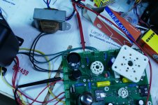
Connect only the green pair of wires from the transformer to the T1-GRN connector, and the yellow pair to the T1-YEL connector. The primary, fuse holder, power switch, IEC inlet, and power cord should be connected as previously used. We are going to test all of this wiring and the transformer.
The red and red-yellow wires should be taped up, or otherwise insulated so they can NOT TOUCH anything...especially you. They produce several hundred volts.
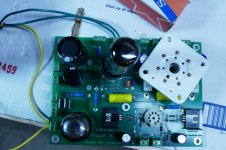
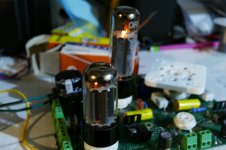
Install the rectifier tube, and one output tube. See the first picture.
With the dim bulb tester in line, power up the board. The tester may glow dimly at first, then show very little glow. Both tubes should have their heaters glowing. See second picture.
Assuming that these steps check out, the transformer and associated wiring are probably OK, and we will test the rectifier and C1.
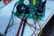
Remove the output tube, leaving only the rectifier tube in the board. Connect the red-yellow wire to the T1-RED-YEL connector, and connect the black meter lead to the other terminal in the same connector. This is circuit ground, so if you can't get a meter probe into the terminal block, connect it to any convenient ground point with a clip lead. Connect the red meter lead to the L1 (choke) connector terminal closest to the T1-RED-YEL connector as shown in the third picture. Alternatively you could connect to the end of R2 closest to the board edge. If you still have the solid state diodes, be cautious of them those metal tabs have high voltage on them. Set the meter to it's highest DC voltage scale, usually 600 or 1000 volts.
Power up the board. The bulb tester may glow briefly during warm up, but should not remain lit brightly or flash. The voltage should rise slowly at first, then climb pretty quickly to around 500 volts. Once at 500 volts there should be a dim glow in the bulb with no flickering. 4th and 5th pictures.
If this doesn't work out, try your other rectifier tube.
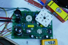
Once you have gotten this far, it's time to connect the choke. Remove the red meter lead from the choke connector and connect both choke wires. place the red meter lead in the left most OPT connector on the rear of the board. Alternatively, you can measure the B+ on the end of R4 closest to the back of the board. See the 6th and 7th pictures.
Power the board up through the dim bulb tester. Things should go as before, with a slow rise, then a steep rise and little glow on the bulb, 8th and 9th pictures.
You have not gotten this far before, so likely you will find a fault somewhere through these tests. Try them and see where the results deviate from what I did here this morning. Then maybe we will have a much smaller area to look at.
If all else fails you can stick the board in a box and send it to me. I will make sure that the board works for the coat of shipping.....I would say sent me the whole thing and I'll fix it, but that's likely to run into issues since you are in Canada and I hear all sorts of cross border extortion and damage stories especially from UPS.
There is about a 90% chance that I will be away from my lab with limited internet access for about 10 days at the beginning of July......that all depends on the virus.
Doesn't the B+ run through the CCS chips?
Yes, it does.....but first it goes through R14 or R24. These resistors are 10K ohms. They will not let enough current through to the CCS chips to cause the kind of problems that you are seeing.
I am wondering if my mains current inrush limiter is simply not getting hot enough to let the current through, due to the fact that the load on the PT is so low
The IRL is a resistor that changes it's value according to how hot it gets. The resistance in the cold state should still allow plenty of power to reach the transformer. That will slowly increase as the part warms up.
Should I even expect "normal" B+ voltages with only the rectifier installed and no choke (and no R1)?
That depends on where you are measuring "B+." If there is no choke or R1, then there should be no voltage anywhere downstream of those parts, which is most of the board. There should be plenty of voltage at the connector that goes to the choke.
There has been some conflicting information in this thread, and I'm not sure exactly what state the board, tubes, or other parts are in, so let's try some simplified "divide and conquer" troubleshooting starting from the transformer.
I grabbed an SSE board in unknown condition from my junk box. It is a very old board which has been used for all sorts of experiments that may end badly. It has been blown up and rebuilt dozens of times in 15 years.....just ignore that monster tube socket in the upper right. It was from a "I need more power" experiment that failed, and will be removed when we get that far.
The power transformer is one that was on my bench for testing TSE boards. It's a bit low in voltage compared to what's usually seen in SSE boards, but it is good enough for use here. My readings are in the 460 volt range without output tubes, where yours should be around 500 volts.
Connect only the green pair of wires from the transformer to the T1-GRN connector, and the yellow pair to the T1-YEL connector. The primary, fuse holder, power switch, IEC inlet, and power cord should be connected as previously used. We are going to test all of this wiring and the transformer.
The red and red-yellow wires should be taped up, or otherwise insulated so they can NOT TOUCH anything...especially you. They produce several hundred volts.
Install the rectifier tube, and one output tube. See the first picture.
With the dim bulb tester in line, power up the board. The tester may glow dimly at first, then show very little glow. Both tubes should have their heaters glowing. See second picture.
Assuming that these steps check out, the transformer and associated wiring are probably OK, and we will test the rectifier and C1.
Remove the output tube, leaving only the rectifier tube in the board. Connect the red-yellow wire to the T1-RED-YEL connector, and connect the black meter lead to the other terminal in the same connector. This is circuit ground, so if you can't get a meter probe into the terminal block, connect it to any convenient ground point with a clip lead. Connect the red meter lead to the L1 (choke) connector terminal closest to the T1-RED-YEL connector as shown in the third picture. Alternatively you could connect to the end of R2 closest to the board edge. If you still have the solid state diodes, be cautious of them those metal tabs have high voltage on them. Set the meter to it's highest DC voltage scale, usually 600 or 1000 volts.
Power up the board. The bulb tester may glow briefly during warm up, but should not remain lit brightly or flash. The voltage should rise slowly at first, then climb pretty quickly to around 500 volts. Once at 500 volts there should be a dim glow in the bulb with no flickering. 4th and 5th pictures.
If this doesn't work out, try your other rectifier tube.
Once you have gotten this far, it's time to connect the choke. Remove the red meter lead from the choke connector and connect both choke wires. place the red meter lead in the left most OPT connector on the rear of the board. Alternatively, you can measure the B+ on the end of R4 closest to the back of the board. See the 6th and 7th pictures.
Power the board up through the dim bulb tester. Things should go as before, with a slow rise, then a steep rise and little glow on the bulb, 8th and 9th pictures.
You have not gotten this far before, so likely you will find a fault somewhere through these tests. Try them and see where the results deviate from what I did here this morning. Then maybe we will have a much smaller area to look at.
If all else fails you can stick the board in a box and send it to me. I will make sure that the board works for the coat of shipping.....I would say sent me the whole thing and I'll fix it, but that's likely to run into issues since you are in Canada and I hear all sorts of cross border extortion and damage stories especially from UPS.
There is about a 90% chance that I will be away from my lab with limited internet access for about 10 days at the beginning of July......that all depends on the virus.
Attachments
-
 P3730210_x.jpg704.6 KB · Views: 310
 -
 P3730208_x.jpg570.4 KB · Views: 306
 -
 P3730212_x.jpg606.8 KB · Views: 295
 -
 P3730213_x.jpg711.7 KB · Views: 285
 -
 P3730214_x.jpg700.6 KB · Views: 290
 -
 P3730215_x.jpg807 KB · Views: 108
 -
 P3730219_x.jpg678.2 KB · Views: 103
 -
 P3730216_x.jpg797.7 KB · Views: 104
 -
 P3730217_x.jpg763.4 KB · Views: 114
Last edited:
Good morning George! Sorry to hear about your ongoing connectivity issues. It seems criminal to me that a company can charge that much for such terrible service.
I didn't have time to tinker last evening and now I am glad that I didn't because the set of test instructions you posted above is going to be extremely helpful! Thank you very much. I hope to have time on Friday to run through these tests and I will report back.
I didn't have time to tinker last evening and now I am glad that I didn't because the set of test instructions you posted above is going to be extremely helpful! Thank you very much. I hope to have time on Friday to run through these tests and I will report back.
Connect only the green pair of wires from the transformer to the T1-GRN connector, and the yellow pair to the T1-YEL connector. The primary, fuse holder, power switch, IEC inlet, and power cord should be connected as previously used. We are going to test all of this wiring and the transformer.
The red and red-yellow wires should be taped up, or otherwise insulated so they can NOT TOUCH anything...especially you. They produce several hundred volts.
Install the rectifier tube, and one output tube. See the first picture.
With the dim bulb tester in line, power up the board. The tester may glow dimly at first, then show very little glow. Both tubes should have their heaters glowing. See second picture.
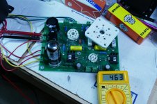
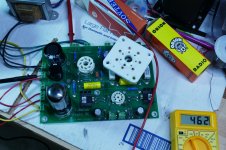
OK. This went well. Exactly as described and shown in your photos.
Assuming that these steps check out, the transformer and associated wiring are probably OK, and we will test the rectifier and C1.
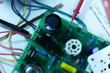
Remove the output tube, leaving only the rectifier tube in the board. Connect the red-yellow wire to the T1-RED-YEL connector, and connect the black meter lead to the other terminal in the same connector. This is circuit ground, so if you can't get a meter probe into the terminal block, connect it to any convenient ground point with a clip lead. Connect the red meter lead to the L1 (choke) connector terminal closest to the T1-RED-YEL connector as shown in the third picture. Alternatively you could connect to the end of R2 closest to the board edge. If you still have the solid state diodes, be cautious of them those metal tabs have high voltage on them. Set the meter to it's highest DC voltage scale, usually 600 or 1000 volts.
Power up the board. The bulb tester may glow briefly during warm up, but should not remain lit brightly or flash. The voltage should rise slowly at first, then climb pretty quickly to around 500 volts. Once at 500 volts there should be a dim glow in the bulb with no flickering. 4th and 5th pictures.
This test failed. Voltage starting climbing quickly but when it got to about 300-350V (don't know exactly) the bulb tester went very bright and the voltage immediately dropped to 3V and I killed the power. I waited 20 seconds or so and powered it on again. This time it only climbed to about 14V then the bulb went bright so I killed it again.
If this doesn't work out, try your other rectifier tube.
Tried 5U4GB. Same. Very low voltage and then bulb tester got bright
So, at this point I am beginning to suspect that the high voltage winding on my PT is shorting or burnt out or whatever. I am going to test it directly with my meter and report back.
UPDATE: High voltage winding tests fine at 375VAC - 0 - 375VAC
So... do I have a fried C1 here?
So... do I have a fried C1 here?
So... do I have a fried C1 here?
That would be my first suspect. If it is possible, remove it from the board and try the test again. If the board powers up (with a much lower voltage reading) and there is no activity on the bulb tester other than a dim glow, then proceed to the choke test without C1. The amp will function without C1, but the voltage will be lower, and there will be hum, but testing can continue.
I have seen resistors (R2) break down under voltage, but they usually make smoke and sometimes flames when they do.
Hello good luck, This is so great to Have George here, your thread is helping me to understand this SSE board.
That would be my first suspect. If it is possible, remove it from the board and try the test again. If the board powers up (with a much lower voltage reading) and there is no activity on the bulb tester other than a dim glow, then proceed to the choke test without C1. The amp will function without C1, but the voltage will be lower, and there will be hum, but testing can continue.
I have seen resistors (R2) break down under voltage, but they usually make smoke and sometimes flames when they do.
I have finally had the chance to continue testing.
I removed C1 and re-ran the test that failed last time.
This test also failed. With 5AR4 voltage went to ~14V and fluctuated a bit. After some time, the light bulb flickered so I killed the power.
I swapped in a 5U4-GB. Voltage got to ~21V and fluctuated a bit. No flickering.
I noticed a smell of hot plastic (?) but did not see any smoke.
By the way C1 tests fine at 49uF.
You are measuring this 14 to 21 volts where? Black lead on ground, and red lead on R2 or the L1 connector terminal closest to the recitfier tube? I am assuming this is true, so, there isn't much left in the path here.
I see two possibilities, neither one seem likely, and I have never seen it happen before.
An internal short inside the power transformer involving the 5 volt winding, or external to the transformer on the wires (yellow on a Hammond) or its Center Tap if present (Yellow with a black stripe) which must remain unconnected.
The little thermistor TR1 could be fried. I have never seen a bad one, but there is always a first time. Examine it carefully and measure its resistance with an ohmmeter. It should be about 50 ohms. If suspect, replace it with a piece of wire and try the test again.
- Home
- More Vendors...
- Tubelab
- Yet Another SSE Build Thread