So here's the chart over the force on a aluminium foil conduit in a magnetic flux density produced in a push pull configuration when it moves from rest level to 1 mm above rest level:


Enlarge it or open the picture in another tab to view it better.
So if only the deviation in percent from the rest level manifests in distortion, there's a clear winner.
Enlarge it or open the picture in another tab to view it better.
So if only the deviation in percent from the rest level manifests in distortion, there's a clear winner.
Last edited:
I thought that I would have gotten my new cutting machine (Silhouette Cameo 5) by know, but it will still be a while.
So I almost finished the rest, in CAD at least.
Here's one of 44 steel plates, 184 mm wide and 200 mm high.
22 magnets, 10x5x3 mm, will be mounted on each steel plate.

A nut bar will hold front and back plates together in three places:

En mutterlist skall hålla samman fram- respektive bakplåt på tre ställen:
A front plate is fastened with a long screw in the nut in te bar. On the protruding rest of the screw, the back plate will be fastened with yet another nut.
Look at the vertical screw holes in the plate above.
The back plate must be wiggled in place.
I will probably not use all screw holes.
The nut bar has also screw holes for supporting side beam.
Here's an attempt to visualize it:
Open in youtube and increase resolution.
So I almost finished the rest, in CAD at least.
Here's one of 44 steel plates, 184 mm wide and 200 mm high.
22 magnets, 10x5x3 mm, will be mounted on each steel plate.
A nut bar will hold front and back plates together in three places:
En mutterlist skall hålla samman fram- respektive bakplåt på tre ställen:
A front plate is fastened with a long screw in the nut in te bar. On the protruding rest of the screw, the back plate will be fastened with yet another nut.
Look at the vertical screw holes in the plate above.
The back plate must be wiggled in place.
I will probably not use all screw holes.
The nut bar has also screw holes for supporting side beam.
Here's an attempt to visualize it:
Well, that didn't go well. The plates bulged in the middle of the mid section by almost an millimeter.
New plate design:

Only five columns of magnets for the mid but now three columns of magnets for the tweeter.
I've also increased the amount of steel between the elongated holes.
The extra holes at the side of each outmost column of magnets are just to be able to temporarily fasten the magnets with zip ties:

So, did the changes help?

Yes, I think so. The largest bulge I can measure is 14.20 mm, that's 0.20 mm from the nominal 14 mm.
What do you think, should I iterate the design further?
New plate design:
Only five columns of magnets for the mid but now three columns of magnets for the tweeter.
I've also increased the amount of steel between the elongated holes.
The extra holes at the side of each outmost column of magnets are just to be able to temporarily fasten the magnets with zip ties:
So, did the changes help?
Yes, I think so. The largest bulge I can measure is 14.20 mm, that's 0.20 mm from the nominal 14 mm.
What do you think, should I iterate the design further?
Yes, this will be the final solution.
So the mid membrane is 63 mm wide.
I couldn't find a suitable corrugator so I had to design my own:
I will make another for the 43 mm wide tweeter membrane.
So the mid membrane is 63 mm wide.
I couldn't find a suitable corrugator so I had to design my own:
I will make another for the 43 mm wide tweeter membrane.
That design is quite beautiful in it's simplicity, I think I will copy that!
The problem at 0:44 where one edge wasn't corrugated can probably be mitigated by making the corrugating wheels slightly wider than the membrane feeder.
I'm curious, did you use ball bearings or without? Looking at building my own corrugator and have planned for ball bearings but not sure if I'm just making everything far more complicated than it needs to be.
Last edited:
I was inspired by this design.
But the corrugation was not right, so I design my own corrugator from scratch except for the handle and the knob.
There are still some dross that need to be removed.
I used 608Z ball bearings. It's actually easier to design with them. Otherwise it'll be plastic against plastic and too wiggly.
But the corrugation was not right, so I design my own corrugator from scratch except for the handle and the knob.
There are still some dross that need to be removed.
I used 608Z ball bearings. It's actually easier to design with them. Otherwise it'll be plastic against plastic and too wiggly.
I must be missing something here, the membrane is moving up and down in the picture above?
Eminent:


My layout:


Eminent:
My layout:
With this corrugator a 400 mm long test aluminium strip is 380 mm at 1 mm corrugation. That's a 0.95 ratio.Yes, this will be the final solution.
So the mid membrane is 63 mm wide.
I couldn't find a suitable corrugator so I had to design my own:
I will make another for the 43 mm wide tweeter membrane.
The effective membrane is 2200 mm but I need some more for the vertical suspension and fastening of the membrane.
The intended gluing board is 2400 mm but practically only 2380 mm long membranes can be glued.
Given the 0.95 ratio a 2260 mm long membrane can then be made.
That gives 30 mm at each end for suspension and fastening of the membrane.
I finally got my Silhouette Cameo 5 Black yesterday, so now it is time to make some membranes.
When I made membranes for my AMTs, I could use a Silhouette cutting mat, but there are no cutting mats that long for the SMAPPP membranes.
So let's do some experiments...
I must be missing something here, the membrane is moving up and down in the picture above?
Eminent:
View attachment 1317384
View attachment 1317385
View attachment 1317386View attachment 1317387View attachment 1317388
My layout:
View attachment 1317389
View attachment 1317390
View attachment 1317391
View attachment 1317392
View attachment 1317393
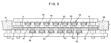
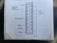
In the ET each magnet is placed down in a welded “U” channel cross frame of steel which gives it strenght from the opposing magnet array
So the magnetic focus line I believe is closer to the moving diaphragm
It was mentioned by them at one time that it wasn’t as efficient as the symmetrical magnet arrangement but preferred it overall and can’t remember their reasoning behind doing it this way
This is from the manual of the ET lft-3
Patent # 4,837,838
I used this "glue" for my cutting matt https://www.computersalg.dk/i/10246...t_gd=F344CCFDC899A7A53458B3DBB57777C3D2D1FFE7With this corrugator a 400 mm long test aluminium strip is 380 mm at 1 mm corrugation. That's a 0.95 ratio.
The effective membrane is 2200 mm but I need some more for the vertical suspension and fastening of the membrane.
The intended gluing board is 2400 mm but practically only 2380 mm long membranes can be glued.
Given the 0.95 ratio a 2260 mm long membrane can then be made.
That gives 30 mm at each end for suspension and fastening of the membrane.
I finally got my Silhouette Cameo 5 Black yesterday, so now it is time to make some membranes.
When I made membranes for my AMTs, I could use a Silhouette cutting mat, but there are no cutting mats that long for the SMAPPP membranes.
So let's do some experiments...
I sprayed it on some 0,5mm plastic sheets
Actually it looked like this
https://www.retailonline.dk/produkt...OcdbdQKR53fRTO58o1bwP9tTN0dN-UARoC1nUQAvD_BwE
Bernt
The orientation of the bottom magnets needs to be flipped if you are trying to emulate US Patent 4,837,838.I must be missing something here, the membrane is moving up and down in the picture above?
Eminent:


My recollection is that arrangement is supposed to provide a more uniform field over the whole diaphragm to address the issue of undriven area in typical planars.
Attachments
I hope that I got it right this time.
There's a constant force up or down (B,n) and most uneven usable force (B,t).


I still doesn't see the benefit of this configuration.
There's a constant force up or down (B,n) and most uneven usable force (B,t).
I still doesn't see the benefit of this configuration.
- Home
- Loudspeakers
- Planars & Exotics
- Yet another Planar Magnetic Line Source, the SMAPPP
