Under what operating condition you measured ten fold THD difference?
I don't remember exactly. I was running on a +/-25 V supply that could supply 1 A, so the output power would have been limited to about 4 W RMS into 8 ohms. I suspect this was the condition I used for the test. Could have been 1 W, though. I'm fairly certain I was measuring at 1 kHz.
~Tom
Square wave test with cap load
Here are some waveforms of square-wave with capacitive load. Output level is 20 Vpp. An output coil with 10R damping resistor is employed.
Here are some waveforms of square-wave with capacitive load. Output level is 20 Vpp. An output coil with 10R damping resistor is employed.
Attachments
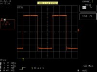
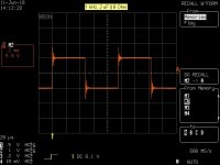
Here are some waveforms of square-wave with capacitive load. Output level is 20 Vpp. An output coil with 10R damping resistor is employed.
Dear Panson,
Thanks for sharing.
Do you also have a 20KHz Square-wave plot on a pure resistive load? I think you should slightly increase the miller compensation to avoid the overshoot.
Of course, more important, we are all curious how does it sound? 😀
With kind regards,
Bas
Do you also have a 20KHz Square-wave plot on a pure resistive load? I think you should slightly increase the miller compensation to avoid the overshoot.
Of course, more important, we are all curious how does it sound? 😀
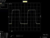
Hi Bas,
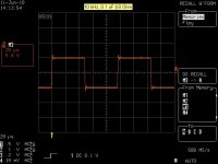
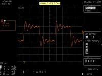
Here is 20 kHz square wave (20 Vpp) without cap load. I currently use 32 pF. I will assemble another board to make a stereo amp for listening.
Panson
Attachments
Hey, 'bas, apropos of the discussion over here I noticed your early schematic shows 100nF || 47uF and later ones 100nF || 22uF. Did you happen to wind up with any comparative data between the two?Thank you Tom for this good explanation. It makes me understand the function of the cap. Did you also experiment with different values?
Final schematics
Folks,
I finally got around to updating the schematic with a few component changes and some annotation. See attached.
The amp has been playing quite happily for months now. The design seems solid. Even after some 8~9 months in service, the bias is still rock solid at 41 mV for the left channel, 42 mV for the right (across 440 mOhm - target value: 40 mV). Given how finicky it is to adjust, my bet is that the bias hasn't moved more than 1 mV from its initial value. That corresponds to 2 mA (or 2 %).
~Tom
Attachments
Last edited:
Hello,
I had to remove the capasitors between bases parallel after Vbe multiplier.Not because stability or something else,but because with the caps the mute control of lme49811 don't 'work correctly. To put in play mode was ok,but when i remove the voltage from sd pin the amp makes the ugly noise.The output goes negative with some ac noise and comes back slowly while my caps discharge. Current to sd pin 1.5ma. Tried sd pin to put to ground momentary as said in datasheet,but no sucsess. Looks like somehow these caps discharge through internal lme circuit after sd is put in mute mode.Without caps mute works fine.Changing from play mode to mute i can hear short click only few inches from tweeter.Anyone experienced this ? I am wondering how in lme49811 mute is implemented?
I had to remove the capasitors between bases parallel after Vbe multiplier.Not because stability or something else,but because with the caps the mute control of lme49811 don't 'work correctly. To put in play mode was ok,but when i remove the voltage from sd pin the amp makes the ugly noise.The output goes negative with some ac noise and comes back slowly while my caps discharge. Current to sd pin 1.5ma. Tried sd pin to put to ground momentary as said in datasheet,but no sucsess. Looks like somehow these caps discharge through internal lme circuit after sd is put in mute mode.Without caps mute works fine.Changing from play mode to mute i can hear short click only few inches from tweeter.Anyone experienced this ? I am wondering how in lme49811 mute is implemented?
Had to put back the capasitors because the performance was degraded. But the mute still mistery not solved.
I started out without the capacitor across the bias spreader, but found that I could get a significant reduction in THD (I think 10x improvement, but I don't recall exact numbers) by adding the capacitor. So I put in 10 uF (I think it was) and left it at that. In his Power Amplifiers book, Bob Cordell includes a bit on why the capacitor is there and how it works. I forget the details, but the gist of it is that the bias spreader should be as close to a voltage source as possible at all relevant frequencies.
You can try to reduce the value of this cap to 1 uF or 100 nF to see if that gives you a good tradeoff between mute functionality and THD.
~Tom
You can try to reduce the value of this cap to 1 uF or 100 nF to see if that gives you a good tradeoff between mute functionality and THD.
~Tom
The STD03N, STD03P output devices are ThermalTrak (TM) devices. This means they have a built-in diode stack on the same die as the transistor itself. So not only is it mounted on the heat sink, it's on the same die attach paddle, and most likely on the same die.
Whether the diode is on the DAP or the die depends on the manufacturer. You'll have to consult with the relevant data sheets or app notes for that information.
~Tom
Whether the diode is on the DAP or the die depends on the manufacturer. You'll have to consult with the relevant data sheets or app notes for that information.
~Tom
Hello,
I had to remove the capasitors between bases parallel after Vbe multiplier.Not because stability or something else,but because with the caps the mute control of lme49811 don't 'work correctly. To put in play mode was ok,but when i remove the voltage from sd pin the amp makes the ugly noise.The output goes negative with some ac noise and comes back slowly while my caps discharge. Current to sd pin 1.5ma. Tried sd pin to put to ground momentary as said in datasheet,but no sucsess. Looks like somehow these caps discharge through internal lme circuit after sd is put in mute mode.Without caps mute works fine.Changing from play mode to mute i can hear short click only few inches from tweeter.Anyone experienced this ? I am wondering how in lme49811 mute is implemented?
Hello, i have the same problem, my LME is to long for enter in PLAY mode, and in mute mode i have an "hmmmm" and négative DC on OUT ...
I have no idea for this problem ... 😕
Tom,
Is there any chance you can publish the PCB layout too, maybe on your webpage as mentioned earlier? It would be a great contribution.
Is there any chance you can publish the PCB layout too, maybe on your webpage as mentioned earlier? It would be a great contribution.
I'm considering tidying up the layout and offering it for sale on my website, actually. It's in the queue behind a few other projects, though.
~Tom
~Tom
I'm considering tidying up the layout and offering it for sale on my website, actually. It's in the queue behind a few other projects, though.
~Tom
Tom,
Any success on the board? I'm seriously considering to test this driver for one of my tiny projects, so your work will help faster than my attempt to do it from scratch. PM me please if you have it done, or post the info here.
Thanks!
- Marat.
No... No progress on this, yet. Great progress elsewhere, though... 🙂 Maybe I should up the priority on this. Let me see how much work is actually involved.
I'll definitely post a note here when I have a good layout and boards for sale.
~Tom
I'll definitely post a note here when I have a good layout and boards for sale.
~Tom
Last edited:
Well, I think it's time to employ one of my students then. 😉
The question is: shall I share the heatsink with power transistors or not?
Pro: extra compact, no long conductors, no need in exotic HS (I'm in Russia), technologically elegant.
Con: no design like this yet, reason unknown. As it's a Class A device with constant quiescent current, it must not depend much on die temperature. Plus, the radiator that is sufficient for such an amp, won't heat or cool fast.
Opinions?..
- Status
- Not open for further replies.
- Home
- Amplifiers
- Chip Amps
- Yet Another LME49811 + STD03 Build