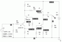
Ok, let's start with a simple common emitter amplifier using the 2SK170 jfet from Toshiba. This circuit is configured for first stage duty. The performance is surprisingly good for such a simple circuit, at least for the low levels encountered for first-stage amplification in an RIAA preamp. As mentioned before, I juggled values to get a first stage gain of close to 40X. The 22k load at the output is due to the initial resistor of the RIAA passive equalization network, which uses 0.1uF for the first break point, 34nF for the second, and resistors scaled accordingly.A resistor value of 22k approximates the load seen by the first stage. The excitation set for the first stage is 2mV to approximate the input from a MM cartridge.
I used PSpice for the simulation. Rel Tol is set at 0.0001, and the step size is set to 1ns. The schematic here shows the circuit and bias values. A PN4391 cascode FET is used so that the cartridge does not see the reverse transfer capacitance of the 2SK170 input jfet. This (the cascode) is pretty much a must for typical MM cartridges, which really care about the loading capacitance. It all adds up, cables, fet input capacitance, and fet reverse transfer capacitance X gain. The cascode pretty much takes care of the last item, but the other two are there in full effect.
Without the cascode, this is the topology used for the first stage of the "Pacific" ultrasimple jfet phono stage, refined by Salas in his popular "Simplistic" thread.
Attachments

Last edited:
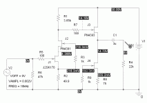
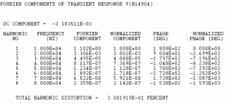
This post shows the simulated THD and harmonic spectrum of the stage noted above. It's pretty good for such a simple circuit. The 2nd harmonic totally dominates, and the higher harmonics are way down. Not bad at all - this is why I chose a variation on this circuit for the input stage shown in this thread. Gain is a little shy of 40X due to the direct loading from the 22k.
Attachments

Ok, so you've seen a design for a simple common source amplifer for the first stage of a phno preamp. Performance looks pretty good, but what else do you need to know? If you're going to tack an RIAA passive equalization network to the output of this amplifier stage, you'll need to know the output impedance of this stage, because it will add to the value of the first resistor of the equalization network, and you need to adjust that value accordingly. The output impedance of a common source jfet stage is the parallel combination of the output impedance of the jfet with the drain load resistor. Cascoding the input jfet increases its output impedance fairly dramatically. For a first approximation , you can assume that the output impedance is simply the value of the load resistor, and adjust the value of the equalization network input resistor by reducing its value.
What if you didn't want to worry about the output impedance of the first stage at all? What can you do? One solution would be to add a buffer. The next circuit shuws just that.
What if you didn't want to worry about the output impedance of the first stage at all? What can you do? One solution would be to add a buffer. The next circuit shuws just that.
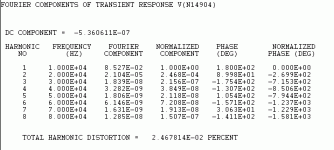
The circuit shown here is the jfet common source stage previously shown, with the addition of a direct coupled current source loaded source follower. The bottom jfet off the follower stage is configured so that it acts like a current sink to bias the top stage. This combination has drastically lower distortion that a source follower using resistive loading. The output impedance of this stage is very low (~50 ohms). Using fets with higher transconductance than the PN4393 (say, a pair of of 2SK170) would yield even lower impedance, but this is pretty good performance from a pair of 35 cent jfets, and allows one to pretty much ignore the impedance of the preceeding common source stage when choosing the first resistor for your passive RIAA equalization network. Is there a penalty? Well, read on.
Attachments
In the previous post, I added a current source loaded source follower stage to the previously described cascoded common source amplifier. This stage isolates the common source stage from the loading of the RIAA equalization network and drives it with a low impedance. Due to the reduction in loading, the gain of the stage is now slightly above 40X, whereas the unbuffered stage had a gain sliightly less than 40X. Use of the buffer to isolate the input stage is appealing from an engineering standpoint, though it was pointed out that one can adjust the first resistor of the RIAA network to compensate for the output impedance of an unbuffered common source amplifier. A simpler input stage is aesthically appealing to some, and some will want to keep the number of stages/parts in a preamp to the minimum.
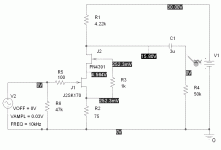
Is there an obvious drawback to adding a buffer? That's not too clear, as the simulation results for THD and harmonic distribution indicate that the buffer doesn't do much of anything to the signal from the preceeding common source stage. Part of the reason for this is likely due to the low signal excursion in this stage.
However, THD isn't the whole story. In order to determine an effect in sonics from the addition of the buffer, one would need to compare the burffered and unbuffered circuits carefully tweaked so that their frequency response is identical, as any difference in equalization will likely mask the sonic differences. I haven't done that yet - maybe you can try it and report back here...
Attachments
I'm going to keep for the time being the common source stage with cascode and buffer as my 40X input stage. There are somewhat more complex candidates with lower THD that could be considered, but let's not overly complicate things at this point - the common source stage with or without buffer is a good use for the ever-scarcer 2SK170.
The actual stage with a lot of distortion issues is the 30X output stage that has to handle line level signals. We'll look at the simple common cathode topology as a line-level output stage before examining other possibilities, and in the process, discover why I considered other circuit topologies for this duty.
The actual stage with a lot of distortion issues is the 30X output stage that has to handle line level signals. We'll look at the simple common cathode topology as a line-level output stage before examining other possibilities, and in the process, discover why I considered other circuit topologies for this duty.
Hi,
as You wrote THD isn´t the whole story, especially as the THD-sims can be very off of the practical values. Just yesterday I had to learn again, that sim and real world differed by app 50dB in THD!! I only use the THD-sim to get an idea about the spectrum of distortions and to see a rough tendency about the quantity.
Basically I´d opt for the simpler circuit, because in my experience lower parts count of active devices resulted in better sound for my ears in most -not all- cases. But the CCS-loaded sourcefollower as buffer is as sonically transparent as one could wish for. Even on my system, which is a extremely sensitive evaluation tool, I can´t really tell any obvious noticable difference between buffered and non-buffered circuits.
In the case here, I´d probabely choose the buffered version, not only because of keeping the gain stage´s impedance out of the calculations, but also to be able to drive the following filter´s caps clean and fast. The gain stage might be short of current capability, while the buffer could drive more current from a lower output impedance into the RIAA-network.
jauu
Calvin
At low level, I'd tend to agree. I like the engineer's viewpoint that the passive RIAA filter wants a low impedance driving it for minimum error, also, a high impedance at the other end.
At least for higher level signals, measurements made with an Audio Precision analyzer at work are in rough agreement with the simulation results for simple circuits like this. It's a tough measurement, as the setup has to be well-shielded and just right, seeing as there can be extra noise from the computer hooked up to the analyzer, as well as the surrounding racket. I'm in a lab environment where people are testing switching power supplies, after all...
It would be a good thing to put together a die-cast Bud box setup with standard ins and outs to make measurement easier. Still, there's the setup for the AP analyzer, not the most user-friendly instrument in the world, especially as you have to deal with what the previous user has done to it.
Last edited:
Ok, I've settled on a 40X common source amplifier with buffer for the first stage of the preamp, and now I have to look at the 30X line-level output stage that gets tacked on after the equalization network. I'm going to start with the same sort of topology as I've chosen for the input stage just to show what happens, then move on to some alternate approaches.
The schematic shown here is the same cascoded common source amp using the 2SK170 as has been discussed previously. I kept the cascode to minimize the amount of non-linear capacitance presented by the fet to the RIAA network (RIAA curve accuracy). The input drive is adjusted for an output of ~1V, a hefty but realistic level.
The schematic shown here is the same cascoded common source amp using the 2SK170 as has been discussed previously. I kept the cascode to minimize the amount of non-linear capacitance presented by the fet to the RIAA network (RIAA curve accuracy). The input drive is adjusted for an output of ~1V, a hefty but realistic level.
Attachments
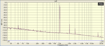
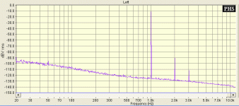
You will note in the previous schematic that I've tweaked the resistor values not only for 30X gain, but to center the drain voltage at ~1/2 VCC for maximum symmetric voltage swing. The THD and harmonic distribution simulation for this circuit is shown below. Though the harmonic distribution is still very clean and totally dominated by the second harmonic, the THD is up by a factor of ~10X. Still, 0.2 to 0.3% THD is not bad for a simple circuit with no global feedback (especially as it's the very benign 2nd harmonic), and driving a 50k pot, no less. Many would be tempted to "declare victory and go home". Many have.
Before moving on to other output stage options, I want to look at the effects of a buffer on this circuit, operating at high amplitude. If one wants to use this kind of circuit in a stand-alone preamp to drive a cable with perhaps lower/unknown impedance peripherals at the other end, a buffer is probably a wise choice for interfacing to the cold, cruel world.
Before moving on to other output stage options, I want to look at the effects of a buffer on this circuit, operating at high amplitude. If one wants to use this kind of circuit in a stand-alone preamp to drive a cable with perhaps lower/unknown impedance peripherals at the other end, a buffer is probably a wise choice for interfacing to the cold, cruel world.
Attachments
Here's the simimulated THD and harmonic distribution, just a tiny bit higher than in the non-buffered case. All harmonics are raised by a small amount, though the only two present in remotely significant quantities are the 2nd and 3rd. It's a small price to pay for the ability to drive a length of cable without significant roll-off
Attachments
Ok, you've seen the THD performance of a simple common source amplifier running at line-level output - a teensy bit on the high side at ~0.3%, but a lot of people are living with it. Check the Salas "Simplistic" thread for evidence of that. Also, this is not bad performance at all for such a simple circuit with no global feedback. However, if you're a guy like me that sweats and fretting all the time to improve things, read on. One possible way of improving on the simple common source topology at high output levels is to increase the bias current such that the amount of load current being driven through the drain load resistance by the signal is a small fraction of the standing bias current, the way it was with the low level version of the common source amp used for input duty . How do you do this and 1) keep the gain you need in this stage and 2) keep the output voltage centered near 1/2VCC? One solution is shown in the "All American" thread I presented a couple of years ago. I'll reiterate that solution here with a couple of variations, but not 'till tomorrow...
Ok, you've seen the THD performance of a simple common source amplifier running at line-level output - a teensy bit on the high side at ~0.3%, but a lot of people are living with it.
Speaking of the 0.3% THD... that's not a lot when we see how they consist of. Important is that we have lowest 3rd and in hearing psycho acoustics the 2nd are harmonics...
Out of topic:
any experience with such circuits for line stages as well, maybe with MOS-Fets?
Interesting, as that's a lot better than the simulations indicate. Perhaps I should try cascading the two stages together with the intervening filter and see what I get. You probably have different gains for the two sections as well.
Last edited:
So I know how to compare things, what are you using for source and analyzer? We have an Audio Precision System Two at work. I may set up a sound card/software based system at home. I actually have enough bits and pieces around to do that.
I tried running a simulation on the composite amp with both stages plus EQ network, and the results are around 0.2% THD 2nd dominant, with all the harmonics beyond the 2nd suspiciously near the same amplitude. I suspect this is the fault of the simulation rather than the circuit, though that needs to be verified somewhere down the pike. I found where I've checked it that the Audio Precision and PSpice have agreed reasonably well for simple circuits. The THD simulation may fall apart for more complex circuits.
Running the simpler circuits at lower amplitude levels results in lower THD - no surprise there, as I would expect a simple common sorce amplifier to have a gradual rise in distortion as a function of amplitude. The high level simulation I showed in previous posts goes from ~0.3% to 0.09% with input level reduced so that the output is 300mV as opposed to 1V.
I think what I'll do is to continue this thread as far as simulating the various pieces that one can use for the second stage, using the THD simulations as a rough figure of merit (higher or lower). Down the line, the next step would be to check on the System Two or other analyzer to see how well the simulations and measurements line up. This will take a while, as I'm also busy working on bringing up a couple of tube amps and this preamp for Burning Amp 2010, which is only a couple of weeks away. I've kept a lot of the boards I've come up with over the course of the past 3-4 years, back to the first cascaded common source preamp that started this investigation - it would be interesting to pop them into a fixture to see how they compare.
The low distortion numbers you report are perplexing, as they are much lower than I would expect for simple common source amps in cascade, even at low amplitude. I actually got a high amplitude number of ~0.3% from a 2SK170 common source amp a couple of years ago with the System Two, which led me to at least trust the simulator values for the simple building blocks as a figure of merit. It also agreed on the with the simulated values I obtained for a cascaded common source amp with feedback that I designed a while back (good simulation/test agreement, lousy sonics - I ended up ripping out the board after an hour of listening and going back to a source follower line amp). Anyway, as they say, food for thought and grounds for further research.
Its repeatable. No doubt. 0.022% again from another member's build and measurements. Maybe its about ''sweet spot'' gate and drain loop cancellation. Use a trimmer for your 2nd stage's Rs and see where it does best. I include a measurement from the 61dB build with 0.3mV input also. If shooting for 1V nominal output the gain would be abnormal with known carts and LP modulations, that's reserve for overload conditions. Has to stay away from clip, but can distort a bit more. My set up you asked about is simple. A 200:1 Lpad 15RZo attenuator at EMU tracker's output, loop the DUT back to its input, use your fav FFT soft.
Attachments
I will continue chipping away with the brute-force Neanderthal THD reduction agenda, until I can verify the interactive distortion reduction you seem to be experiencing. It would be interesting to see if a dedicated distortion analyzer unit like the Audio Precision agrees with the soundcard/software type approach. The EMU tracker you're using is not all that pricey - I may nab one, as it's an external unit, and I haven't tried one of those yet. It may even work with the netbook I have coming later this week. I also have a Terratech DMA 6Fire card, an old (first generation) Echo Gina, and a Turtle Beach Montego II home studio I might try with an older system.
Anyway, I'll be posting on a lower distortion (according to sims) approach to a second stage amp tomorrow. I surprised myself with my first try using a jfet that features prominently in my war chest for cascode duty (I tried it first on a whim), so I may not even try using any small signal mosfets, as they were higher distortion in my last sims (I'll try again with higher resolution) and a pain in the butt to bias, as they are enhancement mode devices (at least the ones I tried).
My current phono preamp is still my second generation SRPP circuit. I've been making improvements down the signal chain, including a discrete jfet crossover and a new set of speakers (Parts Express Tri-Trix kit modified for bi-amping). Negligently recorded material is far less tolerable.
- Status
- Not open for further replies.
- Home
- Source & Line
- Analogue Source
- Yet Another JFET Phono Preamp