When I get around to it, I'm going to source a "clamshell" type ZIF socket so I can actually sort and characterize parts like the BF862 without going out of my mind. The socket will probably be in the range of about $100, but my sanity is worth more.
We probably have a few around for SOT23-6 which work fine.
Of course - all those clamshell-type ZIF sockets are gonna sting you for 100 bucks, unless you're lucky enough to find one surplus.
I'll worry about it when I have time to mess with something new - I have enough projects lined up to last me through next year (wildly optimistic). What's worse, they morph as I get new ideas, so that today's projects are not necessarily tomorrow's. Sisyphus never had it so good...
Last edited:
Maybe Scott has a few surplus ......
(joke of course)
😉
Patrick
I might be able to get some purged for lead content.
Ug the Neanderthal flailed away with his calibrated antelope thigh bone and the direct approach - If you want to reduce the distortion of a common source stage at high amplitude, increase the standing bias current so that the signal current swing is a smaller proportion of the total bias current.
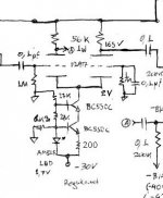
How do you accomplish that wihout having to drastically reduce the drain load resistor (reducing the gain in consequence) or moving the drain voltage away from the desired value of 1/2VCC? The trick is, nobody says that the extra bias current has to flow through the drain load resistor - if you route it directly to the gain device, you still get what you need. The two circuits shown here do just that, adding extra bias current to the gain device using an external current source. I show circuits using two jfets - the J310, a common high transconductance RF device, and the PN4391, a low resistance chopper fet that also makes a good linear device. The PN4391 is usually my first choice for cascode duty, as it will provide 4-5V of headroom at a resonable drain current..
Anyway, cascode fet J2 has a triple duty in both circuits. First, it pins the drain voltage of gain fet J1/J3 to a more or less constant value, reducing the contribution of its reverse transfer capacitance to the overall input capacitance. Secondly, the drain of J1/J3 is now a quiet and convenient point to inject more drain current via a current source. Cheapskates could use a simple resistor in place of the current source and probably get similar benifits - simulate it and see. Third, since the drain voltage of J1/J3 is pinned to a relatively low value, the power dissipation is not excessive, even with the extra current (100mW or so ). For those of you who might whine about the extra current/power, remember that vacuum tube users blow a lot more power in the filaments of even a tiny triode and don't bat an eye about it. The cascode fet still works as it should and provides sufficient headroom for gain fet J1/J3, as it is only handling the current going to the load resistor R2 instead of the total drain current of J1/J3.
There are several approaces that would work for current source I1. A ring-of two current source using PNP devices is straight forward, and a resistor can be added in series with the source to limit the power dissipation in the current-carrying transistor. A depletion mode mosfet might also be usable, and would have a smaller parts count.
Attachments
Last edited:
Here's the simulated distortion plots for the two circuits. The plot for the J310 circuit is on the left, and the one for the PN4391 is on the right. It's no big suprise that the circuit with the highest bias current (the 4391) has the lowest distortion. The harmonic spectra for both are extremely benign, dominated by the 2nd harmonic. The plots are for 1V output.
Attachments
Late-breaking news - the PN4391 circuit looks really nice at the low drive levels at the input. This may shape up to be a simpler, cleaner version of my "All-American" RIAA without the messy bias circuit used for the small signal mosfet originally used in the second stage, and get rid of the 2SK170 in the first stage. Check out the "All American" RIAA thread (searching in just the thread titles does it) to see what I mean. Next up will probably be jfet SRPP when I get a little time to breathe. Check the "jfet SRPP RIAA" thread (search does it again) if you want to do a little homework.
Late-breaking news - the PN4391 circuit looks really nice at the low drive levels at the input. This may shape up to be a simpler, cleaner version of my "All-American" RIAA without the messy bias circuit used for the small signal mosfet originally used in the second stage, and get rid of the 2SK170 in the first stage. Check out the "All American" RIAA thread (searching in just the thread titles does it) to see what I mean. Next up will probably be jfet SRPP when I get a little time to breathe. Check the "jfet SRPP RIAA" thread (search does it again) if you want to do a little homework.
So you've arond 36dB gain in the second circuit, can you share your sonic impressions... how does it sound?
Another point, what about using an BJT for the cascode?
Edit: correction of typing
All american riaa
Jfet SRPP
I really like your current injector approach, nice idea! How do the THD-numbers translate into sonics?
Rüdiger
Jfet SRPP
I really like your current injector approach, nice idea! How do the THD-numbers translate into sonics?
Rüdiger
Folks asking for sonic impressions - The late-breaking stuff is only simulations. Right now, I'm in Burning Amp mode and trying to bring together and debug other projects. I may build some of these combinations and listen to them, and I may not. I'm not even finished delineating the various build options possible, and I may come up with new ones by the time I'm done. I suggest that if you have a real burning immediate need to know about a given circuit, build up the object of your curiosity yourself and report back.
Got to watch noise contribution when injecting in the node. Its not correlated noise but each thing adds up. Maybe just a small size resistor will be wise, not only cheapness.😀
I did that in my tube amp's phase splitter tail cascode CCS (6k8) some time ago. For its ref, but its the same concept.
I did that in my tube amp's phase splitter tail cascode CCS (6k8) some time ago. For its ref, but its the same concept.
Attachments
It wouldn't be really hard to do some filtering on the current source before it hits the cascode node. I'm only really worried about the noise at the first stage if I use such a scheme there. That's if - what I want to do in this thread is lay out the various approaches I've investigated like a deck of cards. They can then be shuffled to heart's content. In the process I may find a few more tricks (you can take the Bridge metaphor if you want, but I don't play).
It would be interesting to try LED biasing. The J310 circuit is just about right for an infrared LED ,and the PN4391 would work with a green. There might be a little too much gain, buT I'd still give it a whack just for the sheer hell of it. People get away with that dodge with tubes all the time.
- Status
- Not open for further replies.
- Home
- Source & Line
- Analogue Source
- Yet Another JFET Phono Preamp