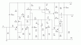
See, we did a little back-and-forth on noise, and the concept morphed at bit - didn't take long, either. I'm adding positions for LEDs on a PCB I'm designing for the current-injection concept (an update to the old "All American" board with room for Russian polystyrenes, which are nice, but kinda klunky).
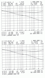
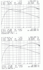
Here's response curves for the RIAA circuit that was posted at the beginning of this thread. The actual board is shown in post #33. Gain matching between the two sides is right on par. This preamp and its accompanying lineamp should have made to Burning Amp last Saturady, but events conspired against me. I'm hooking the box back into my living room ststem tonight to see if I've exorcised all the demons (large and small) that have been plagueing me. I may have to replace the source selector switch, but that's just grunt work.
Attachments
Are they a bit ''hot'' at 20k? Cant be sure I read it well. *-19.6dB ref 1k is the textbook level at 20kHz.
The networks have the 50 kHz zero for "cutter compensation", so as a consequnce, the 20 kHz may be a bit high. I'll have to check. First on my agenda, though, is replacing a no-good source selector switch.
I haven't had good HF whenever I tried the ''cutter'' alignment both in valve and Jfet open loop phonos. Bright. Was playing with a TAG McLaren gimmicky BJT phono once, had a front plate button for that extra constant also, so I could readily A/B it. Bright.
If you're running an MC cartridge, maybe the extra HF attenuation makes a difference. I've still got the Grado Gold, which is probably between an MC and the usual MM cartridge in terms of response. It's easy to short across the extra resistor in practice, and I may try it once I get other pressing concerns out of the way. What I want to do at this point is wire in a new selector switch to my preamp box, as the one I'm using flat doesn't work (or is intermittent) for some reason. Once everything is running, I'll want to take some time to get used to the new box, as I've already had some indications that It'll change the sound of my system yet again, probably for the better.
What I've done in the go-round is to pair up the RIAA preamp with a "Liniac-Like" lineamp with gain. Once I get things configured to my liking, I'll be able to mix and match preamp and lineamp modules without a whole lot of fuss.
What I've done in the go-round is to pair up the RIAA preamp with a "Liniac-Like" lineamp with gain. Once I get things configured to my liking, I'll be able to mix and match preamp and lineamp modules without a whole lot of fuss.
MMs droop. I run a low MC 250uV. Those peak. My best fun with MM is a 100kOhm trimmer and no extra pF for input load. Matches them pretty good for response after hunting high and low. 47k + pF cap is inadequate. Especially for Grado. I would play between 10k-22k for a Grado.
I did a simulation with the Land R values of a Grado and came up with 16k, which is what I'm using for a default value. Once things are settled down, it's time to break out the test record...
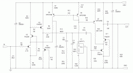
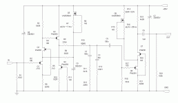
The attached schematic shows one side of another module I've just finished based on the "current boosted common source" principle introduced in the "All American" thread, reiterated here. It's a somewhat simpler version of the All-AM, as it uses a PN4391 jfet instead of a ZNN3306A mosfet in the second amplifier stage, making biasing a bit more straightforward. I also omitted a source follower in the output stage, as it is going straight to a 50k pot. You may choose differently. I originally was trying to use the PN4391 in both the input and output stage, but found the J110 fet a little easier to bias in the input stage. I chose a J110 matched pair that required relatively high bias current to keep the distortion down.
I tested the gain-phase of both sides, and they matched to within 0.5dB - not as tight as my last effort, but still ok. I'll post the scan results when I get back to work Monday, as I didn't get the chance to scan the paper results into the computer. I suspect that the difference is one of absolute gain between the two sides rather than tracking differences between the two RIAA filters, as the filter components are matched very well.
The power supply used is different than the one shown in the beginning of this thread, using a current mirror loaded 2SJ74 diff pair and LED voltage reference instead of the zener-based reference shown at the beginning of this thread. This will be a test of the supply as well as the amp circuit when I load it into my preamp box.
Attachments
I've updated the schematic a bit. I replaced master current source Q9 with an LM317 current source, polluting the precious bodily fluids of the circuit with a nasty IC. However, it was more a accurate current source and had a higher output impedance than the fet I was using. When I find my stash or buy a new bunch at Mouser, I plan to replace the LM317L with a Supertex TO-92 depletion mode mosfet, which should have decent output impedance.
Anyway, U1/Q9 is the master current source for the circuit. Q5-7 are current mirrors that multiply the output of U1/Q9 and direct it to the drain of the gain fet for each stage, Q1 and Q11. Resistors R7, 9, and 22 scale the current going to each stage. I may revamp the circuit to use two separate depletion mode mosfets as current sources, one for each stage. It's fewer (but more expensive) parts, and I would appreciate a little less clutter. It also modularizes the design, making it easier to separate and bring up each stage.
I played with the idea (in simulation) of using an LED at the source of Q1 instead of a resistor, modelling it roughly with a voltage source and series resistor. Gain and distortion are higher, as the local feedback is much lower due to the lower impedance of the LED. I may try this approach later on, as the distortion, though higher, is almost entirely 2nd harmonic, and is similar in magnitude to that of a simple 2SK170 input stage. Using the resistor instead of an LED trades off less distortion in turn for a bit more noise.
Attachments
Last edited:
I replaced master current source Q9 with an LM317 current source, polluting the precious bodily fluids of the circuit with a nasty IC.
😀
When pumping the cascode's lower floor common source current gain part with a CCS, is there any gain in PSRR for the whole cascode?
I don't know if the added current does anything to the PSRR. I could try wiggling the VCC voltage in simulation, but that may not be terribly conclusive. Best to assume that the cascode pretty much trashes the PSRR due to the current divider effect between the high impedance cascode fet drain and the load attached to it, and try to arrange for as quiet a VCC supply as possible. This is a good approach anyway - if you don't track dirt into the house, you don't have to sweep it out...
I'm going to look around tonight in the basement and try to find an appropriately sized die-cast aluminum box so that I can make a permanent well-shielded test jig to use with the AP or whatever other sort of analyzer I gin up. Distortion measurements with the RIAA preamp will be pretty much meaningless until I come up with some decent shielding, and I might as well take the trouble to make a proper jig so that I can easily pop boards in and out, attach test points, etc. I have a box put together with copper tape and copper-clad board, but it's a pain to deal with, and I don't quite trust it.
This afternoon will hopefully be spent in the final stages of bringing up another tube amp, another vacuum/jfet hybrid.
I was thinking of using an outboard usb interface for audio measurements with my new netbook, but it looks like there very few makers of those rigs that have Linux drivers, and my netbook runs Ubuntu Linux. Anyone have any suggestions for an outboard sound card that will run Linux and is of sufficient quality to use in audio analysis?
Hi,
have You by any chance simmed the noise? Active sources -as the current sources in this example- may introduce considerable noise to a circuit.
jauu
Calvin
have You by any chance simmed the noise? Active sources -as the current sources in this example- may introduce considerable noise to a circuit.
jauu
Calvin
I'm going to look around tonight in the basement and try to find an appropriately sized die-cast aluminum box so that I can make a permanent well-shielded test jig to use with the AP or whatever other sort of analyzer I gin up. Distortion measurements with the RIAA preamp will be pretty much meaningless until I come up with some decent shielding, and I might as well take the trouble to make a proper jig so that I can easily pop boards in and out, attach test points, etc. I have a box put together with copper tape and copper-clad board, but it's a pain to deal with, and I don't quite trust it.
Cookie tins are great for this application -- you can get the big ones at Costco -- and place a smaller one inside. A big cookie tin by itself, however, is a big capacitor, and it's got to be grounded to the test instrument.
I think that Scott mentioned that he had double shielded for his JFET measurements AND placed the rig in the center of the room.
I found one of my die-cast aluminum boxes and fitted it with isolated RCA in and out jacks, as well as a dedicated ground screw bonded securely to the case via a kep net and lock washer. I added ez-hooks to the connectors inside so I can quickly swap boads in and out. I'll eventually have two sets of hole patterns to fit my standard board sizes for RIAA preamps and line amps.
Last edited:
Audio Research PH3 Hybrid phono pre amp
Hello Wrenchone & others,
First time writer here.
I have seen discussions about phono pre amp using JFET.
I am a tube DIY (wanabe, at least) and have very limited knowledge about transistors. I am planning to build a phono pre amp using the Audio Research PH3 topology. However, I can't identify the Q1 & Q2 (same) JFET used in the first stage. I can't cross reference to Fairchild, Toshiba, Motorola or Vishay part numbers. Can you help me out in this ?
The ARC PH3 schematic can be viewed here :
ARCDB - PH3
Thank you,
Ken
Vancouver, BC Canada
- Status
- Not open for further replies.
- Home
- Source & Line
- Analogue Source
- Yet Another JFET Phono Preamp
