Back to the drawing board
Have tried to fit the VC in the gap.
Ideally, the gap is 4 mm and the VC 1,5 mm, so there a little more than 1 mm margin on each side of the VC.
So for sure, I can make it fit, but there will be no margins in any direction.
And the reality isn't ideal along the 500 mm long gap.
The VC is 4 mm in height so Xmax is modest too, only 3 mm ((10 - 4)/2).
Don't panic!
New magnet assembly coming up:

The iron in the gap has changed from 3x10 mm to 2x15 mm.
This gives 2 mm of additional space in the gap (6 mm - 1,5 mm) and a longer Xmax (15 - 4 / 2 = 5,5 mm).
This comes at a cost of a lower field:

But only 35 % lower (new gap to the right):

I have also simulated 1,5x15 mm, that is a gap of 7 mm:

It would work as well and is perhaps preferable, but that thin rods are hard to come by; you'll have to make them out of 1,5 mm steel sheets and then hard to get straight.
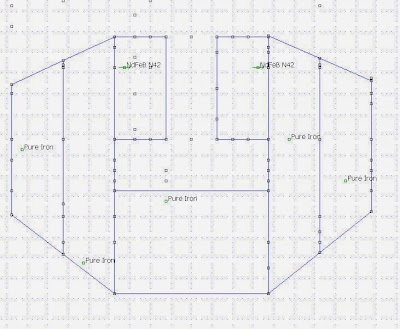
New magnet assembly coming up:
The iron in the gap has changed from 3x10 mm to 2x15 mm.
This gives 2 mm of additional space in the gap (6 mm - 1,5 mm) and a longer Xmax (15 - 4 / 2 = 5,5 mm).
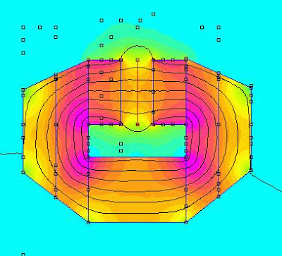
This comes at a cost of a lower field:
But only 35 % lower (new gap to the right):
I have also simulated 1,5x15 mm, that is a gap of 7 mm:
It would work as well and is perhaps preferable, but that thin rods are hard to come by; you'll have to make them out of 1,5 mm steel sheets and then hard to get straight.
Member
Joined 2003
I´ve been doing simulations on such circuits in the past and even if the field is stronger they are more suitable for ribbons as they have less linear excursion.
They are also harder to build.
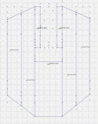
Do you mean something like this:
They are also harder to build.
Do you mean something like this:
Maybe like this:
 [/IMG]
 [/IMG]
 [/IMG]
 [/url][/IMG]
 [/url][/IMG]
It is 5x10mm neo ,5mm gap.
But maybe you dont need a fieldstrength that strong.
It is a very long field compared to a "normal" speaker.2" voicecoil app.160mm.
Bernt
It is 5x10mm neo ,5mm gap.
But maybe you dont need a fieldstrength that strong.
It is a very long field compared to a "normal" speaker.2" voicecoil app.160mm.
Bernt
Last edited:
Agt would you want to limit it ? If it's even then it is ok or am I missing something ? If you want lower field strength you can increase gap or use cheaper magnets ?
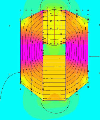
If the iron is not saturated and thus not limiting the "current" you would get a non-linear field in the gap:
The max strength will be the same though on account of the gap length.
The max strength will be the same though on account of the gap length.
Last edited:
I will have take back the saturation theory.
When I simulate this circuit I get the same non-linearities as in my other simulations:


I think your simulation is flawed, could you please double check?
This looks for instance a little fishy at the steel to magnet surface:
Maybe the properties for the magnet are set to the wrong values, it seems no saturate at 0,8 T?
It could of course be me that are wrong; nevertheless the design must be based on correct simulations whoever is "right".
When I simulate this circuit I get the same non-linearities as in my other simulations:
I think your simulation is flawed, could you please double check?
This looks for instance a little fishy at the steel to magnet surface:
An externally hosted image should be here but it was not working when we last tested it.
Maybe the properties for the magnet are set to the wrong values, it seems no saturate at 0,8 T?
It could of course be me that are wrong; nevertheless the design must be based on correct simulations whoever is "right".
Ok, so where was this measurement made?
An externally hosted image should be here but it was not working when we last tested it.
Ok it is in the gap.
But the points are placed 2.5mm before the gap and 2,5mm after. 15 mm. measured total.Not 10 mm.
Bernt
But the points are placed 2.5mm before the gap and 2,5mm after. 15 mm. measured total.Not 10 mm.
Bernt
Yes, I understand that and it is of no significance.
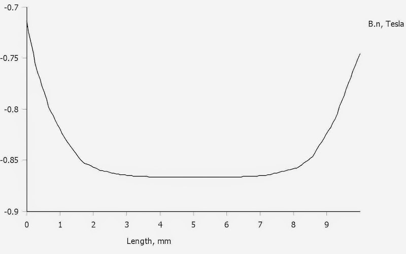
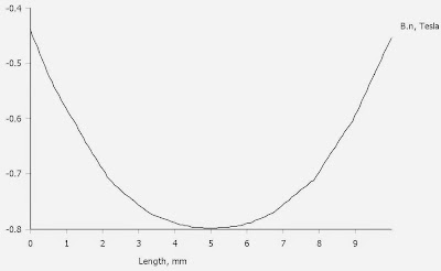
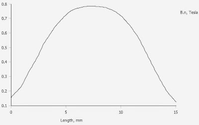
What is strange is this portion of the plot:

I doubt that the field is linear in the gap (2,5 to 12,5 mm) and also outside the gap (0 to 2,5 mm and 12,5 to 15 mm).
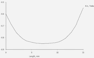
This is the 0 to 15 mm plot for my simulation:
What is strange is this portion of the plot:
I doubt that the field is linear in the gap (2,5 to 12,5 mm) and also outside the gap (0 to 2,5 mm and 12,5 to 15 mm).
This is the 0 to 15 mm plot for my simulation:
It is strange.
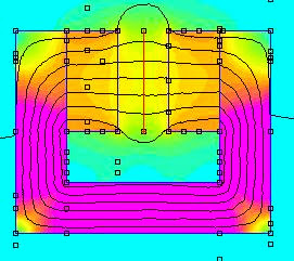
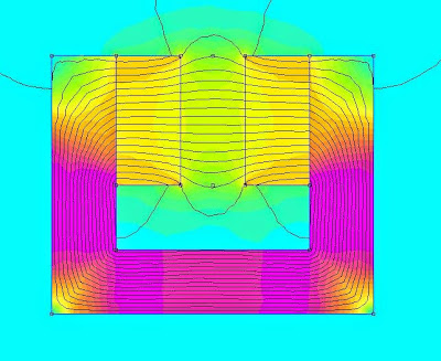
Here you see 2 sims:
 [/url][/IMG]
 [/url][/IMG]
On the second Picture you see how the measuring points are disturbing the fieldlines.
Bernt
Here you see 2 sims:
On the second Picture you see how the measuring points are disturbing the fieldlines.
Bernt
Last edited:


- Status
- Not open for further replies.
- Home
- Loudspeakers
- Planars & Exotics
- Yet another DIY Planar Bass