Went to the kitchen
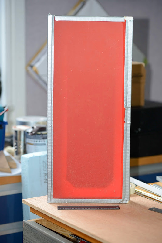
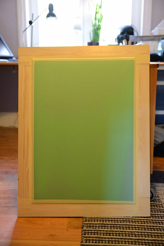
Cut a membrane from a baking sheet.
It is 1,25 mm thick. Mounted it on a wooden frame:
Applied a pieced of foam board (here it is only setup for the picture):

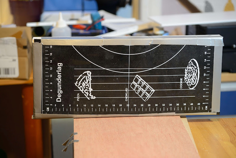
Put the frame flat on the table and rigged a ruler:
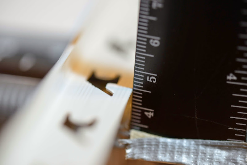
Added 100 gram. Not evenly distributed, though:
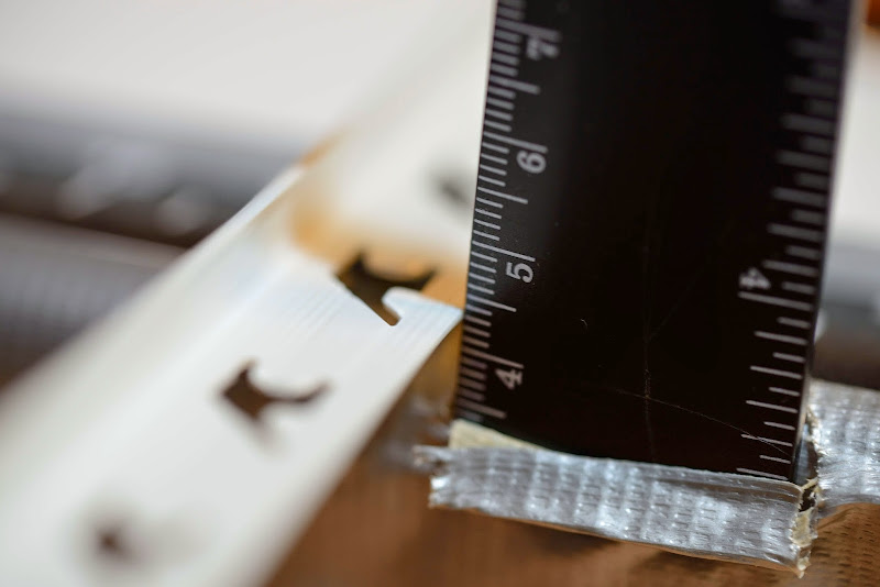
Added another 100 gram. Had to shift the first weight, so the membrane didn't move that much:
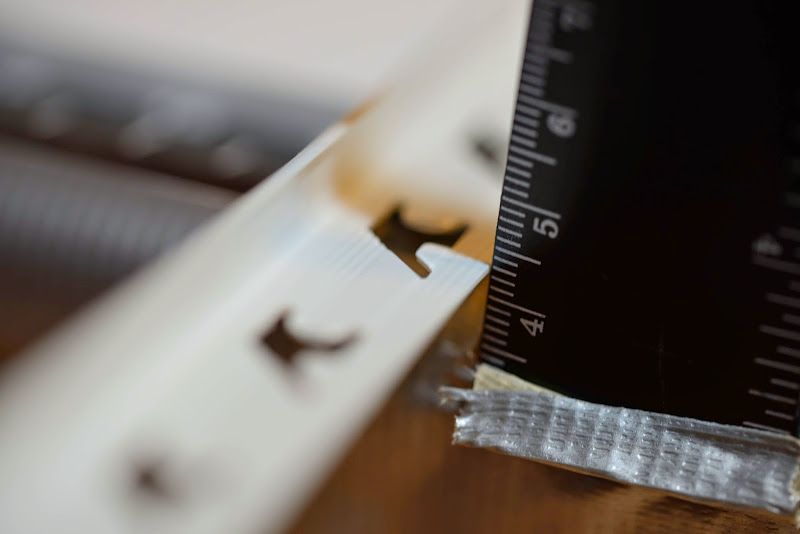
300 grams:

400 grams:

So the movement is roughly 1 mm per Newton.
I will make more extensive tests later with a better mounting of the baking sheet and also have better distributed weight and more gauges.
I would say that this looks pretty good.
Please correct me if I am wrong.
Cut a membrane from a baking sheet.
It is 1,25 mm thick. Mounted it on a wooden frame:
Applied a pieced of foam board (here it is only setup for the picture):
Put the frame flat on the table and rigged a ruler:
Added 100 gram. Not evenly distributed, though:
Added another 100 gram. Had to shift the first weight, so the membrane didn't move that much:
300 grams:
400 grams:
So the movement is roughly 1 mm per Newton.
I will make more extensive tests later with a better mounting of the baking sheet and also have better distributed weight and more gauges.
I would say that this looks pretty good.
Please correct me if I am wrong.
Another sheet
Rigged another baking sheet, this time 1 mm thick. Front view:
and back:

This sheet seemed to have about 0,5 mm/N but had more initial saggidness when placed horisontally.
Having vertical, as in the pictures above, doesn´t seem to produce any saggidness at the buttom of the membrane.
Having the membrane vertical doesn´t produce an asymmetrical response as opposed with a horisontal membrane; fight the gravity on its way up and ride along with it on its way down.
So perhaps this is the way to go. Just cut the complete loudspeaker in two and rotate each part 90 degrees and place on top of each other.
Rigged another baking sheet, this time 1 mm thick. Front view:
and back:
This sheet seemed to have about 0,5 mm/N but had more initial saggidness when placed horisontally.
Having vertical, as in the pictures above, doesn´t seem to produce any saggidness at the buttom of the membrane.
Having the membrane vertical doesn´t produce an asymmetrical response as opposed with a horisontal membrane; fight the gravity on its way up and ride along with it on its way down.
So perhaps this is the way to go. Just cut the complete loudspeaker in two and rotate each part 90 degrees and place on top of each other.
The tape is 0,04 mm thick. I need an insulation kapton tape between each layer.
The kapton tape is also 0,04 mm. That's 0,08 mm a layer.
To get 8 ohms, I need 4x8 layer if 1 meter equals one layer.
So the VC will be 2,56 mm thick plus the VCF giving a grand total of 3,56 mm in a 4 mm gap. It won' t fit.
The VC will be 3 mm wide (or deep?) of course.
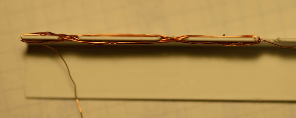
Using 0,25 wire I need 23 turns to get 8 ohms. If I can have 12 turns on the inside of the VCF and 12 turns on the outside, the voice coil will be 1,5 mm thick and 3 mm wide/thick.
That would fit in the 4 mm gap.
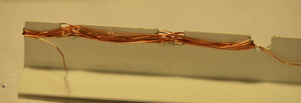
Here is my first attempt on the feasibility of making a VC with 0,25 mm wire. There's a long way to go...
Are your magnet poles going to be alternating as per section?
NSNSNSNSNSNS
-------------------
SNSNSNSNSNSN
VS.
NNNNNNNNNNN
------------------
SSSSSSSSSSSS
The VC in the pictures is just a test of how it would fit in the VCF, not how it will actually will be wired.
The finished VC will be wired as in an ordinary VC and the magnetic poles will be as in an ordinary driver:
O goes into a ( ) that goes into I I
The finished VC will be wired as in an ordinary VC and the magnetic poles will be as in an ordinary driver:
O goes into a ( ) that goes into I I
Okay, Cool !!
I have given something like this a lot of thought through the years and I am very interested in seeing your end results.
I have been contemplating what I could use as a surround material such as thin rubber balloon material to using actual long balloons ( animal figure type) filled with nitrogen or something to get a good Xmax.
Then I was thinking to use an aluminium bar to put the voice coil on, as this would also help to create some dampening when it is in the magnetic field and act as a heatsink for the VC.
Just a few thoughts.
Cheers!!
jer 🙂
Thanks!Okay, Cool !!
Me too! It will be a bumpy ride and there are a lot of problems to solve.I have given something like this a lot of thought through the years and I am very interested in seeing your end results.
Even though this is an OTS product and thus in a ugly color, I think this silicone rubber is the material to use (it could have been larger though).I have been contemplating what I could use as a surround material such as thin rubber balloon material.
There are more variants to test of course.
I think it will be hard to get the perfect silicone rubber and even if it existed it will not be OTS.
You might get a sample from a factory but then you would probably have to buy 1000 square meters.
Group buy anyone? Just kidding.
As I want an underhung VC, that is that the complete VC always is in a wide field (an overhung VC has parts of it in a narrow field), linear Xmax can never be less than (gap length - VC length)/2. So with a 10 mm gap and a VC of 2, there´s only 4 mm left. So why aim for more?... to get a good Xmax.
Vd will still be huge having a huge Sd.
From Wikipedia :

I think that an overhung VC, being that wide, is very hard to do by yourself.
Also a high field is more difficult to accomplish.
I´d say that an underhung VC is the only option here.
As the coil is distributed and almost a meter, I don´t aluminium is necessary. Do you have any practical results that you would like to share?Then I was thinking to use an aluminium bar to put the voice coil on, as this would also help to create some dampening when it is in the magnetic field and act as a heatsink for the VC.
Last edited:
I was thinking of the dampening when I had observed what was on a grain scale I once had.
It was just a couple of magnets and a piece of thin aluminium plate mounted on the end of the teeter totter, It was very effective!!
I also played with magnets sliding down a large copper clad PCB material and copper pipes, this really amazed me.
Using a light rubber surround won't give it much compliance, I had thought about using Silicone as well but making a mold and forming it is a bit of a PITA, as it is so sticky and messy to work with.
Then I discovered the flowable kind a few years ago that may be easier to work with once a mold is formed.
Maybe even use it with a cloth based corrugated accordion style suspension saturated with it or something.
I suggested that it be mixed with a silicone oil to make it softer for use in the repair of the rotted foam issue of the Apogee Duette's.
Someone tried it and it worked!!!
As far as the Xmax my main concern was not so much about how much, but keeping the travel linear as the suspension starts to pull more on the diaphragm towards the end of its outter travel.
Then employ a servo type of control, possibly.
This may very well not be much of an issue as you mentioned due to the very large Sd.
I haven't made any models or attempts at this as I don't have enough magnets yet, so they are mostly ideas.
Then I got into ESL's.
My goal was then to build a small compact dipole bass system with a very large displacement to be used with my Desktop ESL design (or even a larger model).
Something like 2 sq.ft. of Sd with eight or more or so 4" to 6" square (or rectangular) panels in side it.
More like a Cube shape on the bottom and the ESL on the top, as the ESL is only 10" to 12" tall.
The shapes are undecided at this point.
Considering how the little 5 1/4" sealed driver I am using now performs, the equivalent Vd times 8 should do well for a small dipole.
Even if it does take a bit of power to run it.
At this point all I care about is moving enough air for my desired SPL.
I have many ideas but I can't do anything unless I build something and see how it performs. 🙂
There were a few threads on such discussions a couple of years ago and was something I came up with too at nearly the same time while I was forced to have some time to think back in 2006 (Without the internet He,he,he,he). 😉
I hope some of my ideas can be of use to you.
I still have those original drawings somewhere, they were originally to use a bunch of folded and/or stacked ESL panels to increase the displacement for a bass driver system and drastically reduce the overall footprint. 😉
Since it was to be a dipole system....Displacement rules !!!!
FWIW
jer 🙂
Thank you jer for your thoughts.
I´ve tested silicone molding, RTV/HB, to impregnate some cloth.
But the tests were unsuccessful. The corrugation didn´t sustain and it was hard to actually get the cloth impregnated.
I also tried Liquid Latex with even worse result.
I have also tried the 3M 74 film:
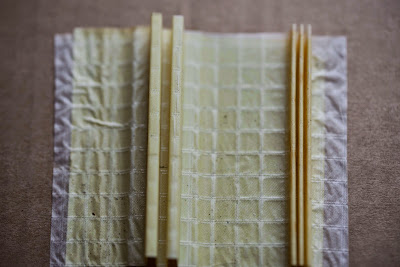

but I doubt that the corrugation will be strong enough to sustain the VC and VCF.
In this context, what is a PITA anyway?
Interesting with the dampening property of aluminium in the magnetic field, but wouldn´t that just increase the distortion and also perhaps heat the VC instead of cooling it?
From the VC Wiki page:
"Aluminium was widely used in the speaker industry due to its low cost, ease of bonding, and structural strength. When higher power amplifiers emerged, especially in professional sound, the limitations of aluminium were exposed. It rather efficiently but inconveniently transfers heat from the voice coil into the adhesive bonds of the loudspeaker, thermally degrading or even burning them. Motion of the aluminium bobbin in the magnetic gap creates eddy currents within the material, which further increase the temperature, hindering long-term survival."
I agree upon the strive to keep the Xmax linear thoughout the VC´s motion in the field.
If one doesn´t succeed, what harmonics will be produced?
I´ve tested silicone molding, RTV/HB, to impregnate some cloth.
But the tests were unsuccessful. The corrugation didn´t sustain and it was hard to actually get the cloth impregnated.
I also tried Liquid Latex with even worse result.
I have also tried the 3M 74 film:
but I doubt that the corrugation will be strong enough to sustain the VC and VCF.
In this context, what is a PITA anyway?
Interesting with the dampening property of aluminium in the magnetic field, but wouldn´t that just increase the distortion and also perhaps heat the VC instead of cooling it?
From the VC Wiki page:
"Aluminium was widely used in the speaker industry due to its low cost, ease of bonding, and structural strength. When higher power amplifiers emerged, especially in professional sound, the limitations of aluminium were exposed. It rather efficiently but inconveniently transfers heat from the voice coil into the adhesive bonds of the loudspeaker, thermally degrading or even burning them. Motion of the aluminium bobbin in the magnetic gap creates eddy currents within the material, which further increase the temperature, hindering long-term survival."
I agree upon the strive to keep the Xmax linear thoughout the VC´s motion in the field.
If one doesn´t succeed, what harmonics will be produced?
He,he,he,he,he,......PITA can't typed here some times just typed as PIA, 😉
Urban Dictionary: pita
I am not sure of all of the effects of dampening with Aluminium would cause.
But I do know that shorting rings are used in some drivers, I am not sure if they are exactly the same, but they can reduce THD as well from what I have read.
I expect due to its dampening property's !!?
I think that what ever heating occurs in the aluminium damper it will be much less than what is generated in the VC itself.
In recent designs I have seen some drivers that have extended the Alu. former to a Alu. heatsink type of dust cap contraption.
I had thought that something similar could be employed by using a heavy gauge ALU foil glued to the surface of the diaphragm if it is of a rigid type.
I can get here some foam panels that already have some Alu. foil applied to it.
Then again I have though about using the material and etch the VC from the ALU directly.
But, It's what type of surround material that could be used has me stumped for the moment.
In the past I have asked these types of questions before from those in this forum that claim they design and build speakers and I got no answer and the threads just end at that point!
Because know one wants to give their secrets or offer any bit of help at all.
The point of the matter is that we are trying to design a square/rectangular speaker and only round surrounds are readily available for replacement of broken drivers. 🙁
I say "If there is a Will, There is a Way" and we will eventually figure it out!!!
Just as was done with the Apogee repair trick that has saved a few Big $$$ already by not having to replace the entire diaphragm (and myself once I get the silicone oil and glue).
Another thought, have you considered using some ALU tape for the VC as it will be much lighter and with its thinness will allow you more turns (layers) within a given space in the gap and still be able to handle a lot of current.
This will also help with the binding of going around the sharp corners like you have with thicker round wire.
You could use copper for easier connection but it is 3x heavier as well than ALu.
Conductive paint works great for connections to Alu!!
I used it once to repair my Duette's with a jumper and the paint 15 years ago and it is still holding mechanically well!!
Has Never came off yet!! 🙂
It could be wound with a layer of thin .5 to 1mil mylar or even Kapton to prevent from shorting between the layers from the heat.
I have experimented also with coating the aluminium strips with some Acrylic enamel spray paint for an insulator and this seems to work well also.
Again, I never made a finished model though.
Hmmmm.....Maybe a few layers of tissue paper material such as that used for wrapping gifts and some rubber/silicone would give some more strength and compliance or even a composite of papers and cloth.
jer 🙂
Oh, I knew about the common interpretation of PITA, I just thought it was some new compound like PTFE.
Yes, I have thought about using aluminium tape and my first try to do this coil was made with that, but it got too thick.
With 32 turns of OTS 3 mm wide aluminium tape, 0,04 mm thick, together with 0,04 mm kapton tape, the VC will be over 3,50 mm thick. And that´s to thick for the indended gap of 4 mm.
One turn of AWG30 copper wire is 0,25 mm thick, but so is also 12 turns.
With the former, 0,8 mm, the VC will be under 1,50 mm having dual layer of winding to get the desired 8 ohms but still only 3 mm wide.
The copper will weigh 10 grams but the VCF is 30 grams and the membrane is about 100 grams with the foam board so it is well below of 10 % of the total weight.
But I haven´t done a full scale test on the copper wire VC, so I might reconsider.
I will then have your ideas in mind for sure.
In the end, the VC problem will be solved.
I agree with you about the well kept secrets of the surrounding; each manufacturer seems to have their own mixture of glue and surround materials.
But I am quite convinced that silicone rubber is the way to go together with foam board reinforcement.
(Who would have guessed that foam board can be used in loud speakers for other reasons than Cornus!)
Hopefully I will have a full scale test of that soon to.
Very Cool!!
I had in mind one more material for the surround and I started to investigate it but again I got side tracked....Foam!
Some type of foam material, Closed or open cell, Like the kind that seat cushions and weather stripping is made of.
The only drawback of some types is that they are very porous and would need to be sealed with some type of thin film.
And the possibility of deterioration over time....Hmmmmmm.......
But it is very springy but seems to be well damped as well.
I just never pursued it any further because of the many projects I already have on the table.
Cheers!!
jer 🙂
It is not just foam, it is foam board.
Here´s Wiki again:
"It consists of three layers — an inner layer of polystyrene foam clad with outer facing of a white clay-coated paper."
The foam board I am using is 5 mm thick.
It supports the VCF with one surface and thus pushes the membrane with the other.
But its main function is to keep the wobbly silicone rubber rigid for the sound reproduction.
Yes, I have some of that foam too.
I was talking about using the spongy stuff for the surround. 😉
jer 🙂
I was talking about using the spongy stuff for the surround. 😉
jer 🙂
Ok. Then there are several foam packaging materials or floor dampening foams to consider.
In fact, I made this with floor dampening foam in my first tests:
Not much Xmax though but it made a nice drum.
In fact, I made this with floor dampening foam in my first tests:
Not much Xmax though but it made a nice drum.
No AMT, no Ripole. Just a plain planar bass.
The project has shifted a bit.
It will not be any bass AMT nor a muliport ripole.
It will be a plain planar:
16 rows of magnetes/steel will make 8 drivers with a attached VC to each that is glued to one membrane.
The project has shifted a bit.
It will not be any bass AMT nor a muliport ripole.
It will be a plain planar:
16 rows of magnetes/steel will make 8 drivers with a attached VC to each that is glued to one membrane.

Membrane shape
Thanks Mooly.
Now the title more reflects the project; it would have been sad to lose the history.
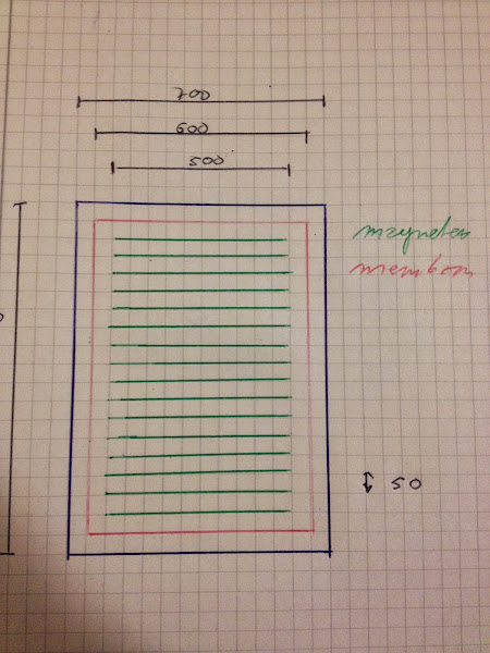
In order to "lower the Q" of the fs, edge/beaming and dipole roll-off, I am now thinking of expanding the membrane from its original 60x80 cm to an irregular shape (each square is 5x5 cm, both left and right membranes/baffles are shown):

The fs is not directly tied to the dimension, but as a wider membrane will be heavier the fs will be lower. Provided that the response can be considered to be local enough. I guess that has to do with how stiff the membrane will be and if the VCs will be individual or not.
Thanks Mooly.
Now the title more reflects the project; it would have been sad to lose the history.
In order to "lower the Q" of the fs, edge/beaming and dipole roll-off, I am now thinking of expanding the membrane from its original 60x80 cm to an irregular shape (each square is 5x5 cm, both left and right membranes/baffles are shown):
The fs is not directly tied to the dimension, but as a wider membrane will be heavier the fs will be lower. Provided that the response can be considered to be local enough. I guess that has to do with how stiff the membrane will be and if the VCs will be individual or not.
It will be like a bookshelf with each shelf having one of these drivers:
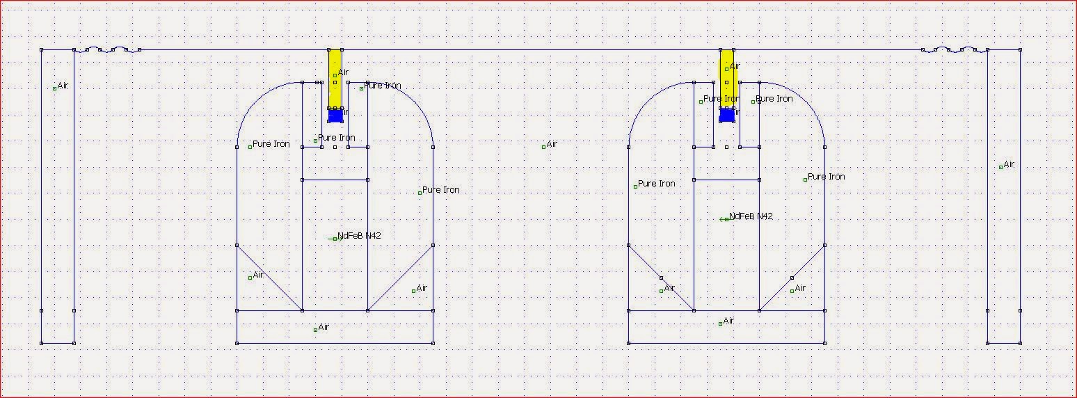
Yellow/blue part is the voice coil.
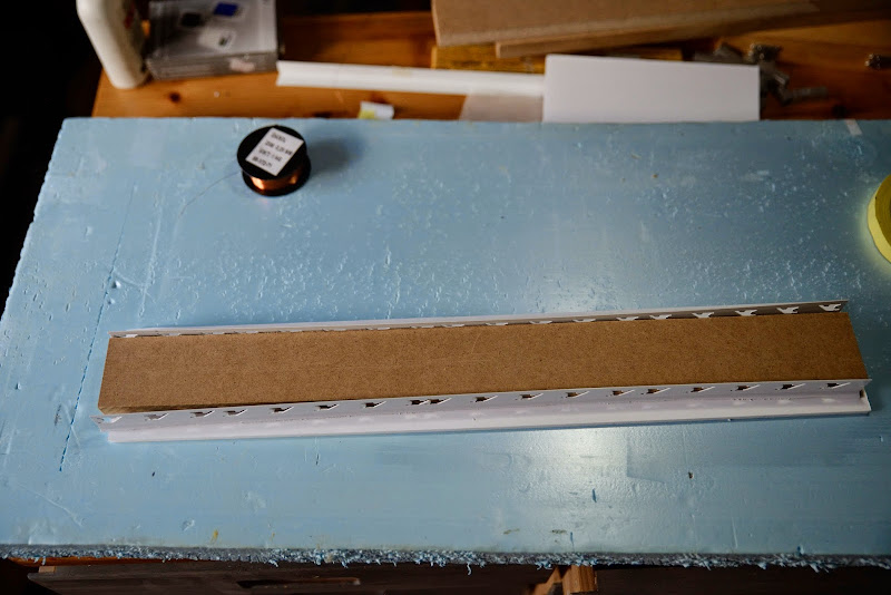
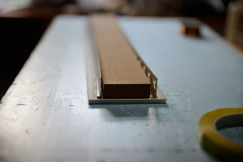
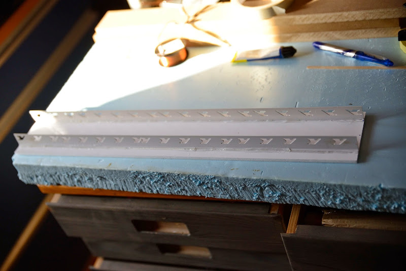
First attempt on the VCF:
the piece of MDF board is just there in order to fasciliate the mounting:

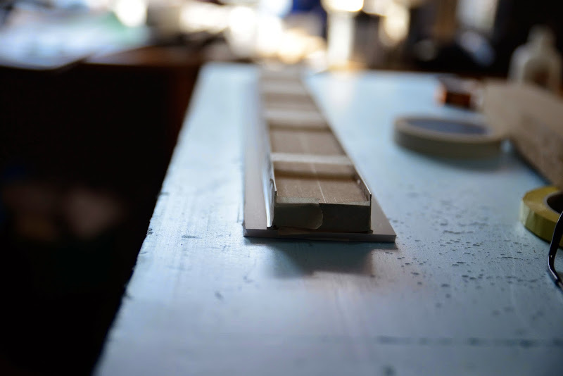
The membrane "pusher" for one segment of the total membrane is 80x510 mm:
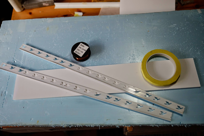
20 turns of 0,25 mm copper wire should give about 8 ohm. 10 % of it will be waste as the wire is outside the magnetic field on the sides.
Hopefully will the picture below speaks for themselves:


Adding the wire
First 10 turns:
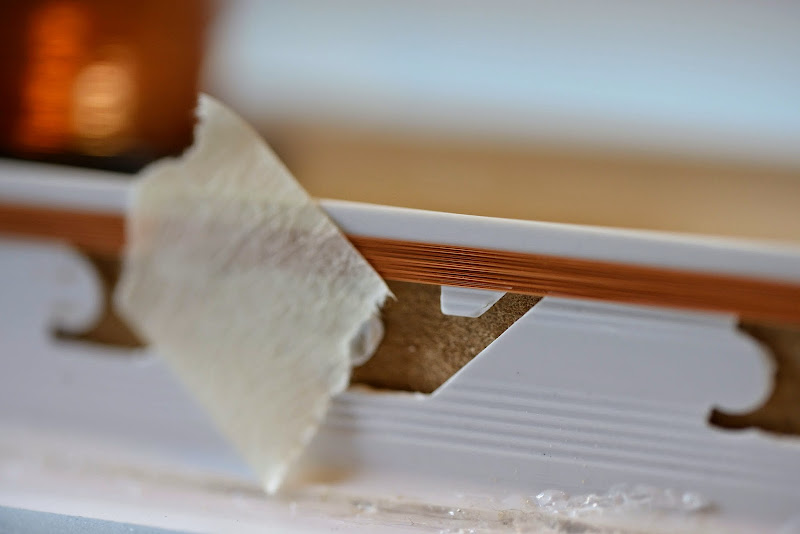
Need to fixate the wire before applying the 74 film:
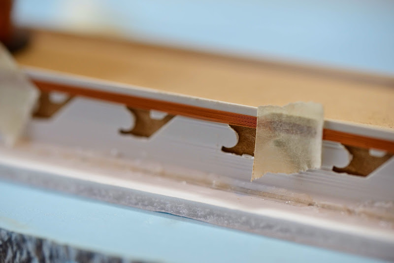
Next layer:

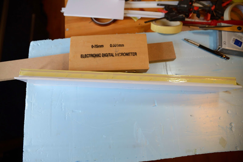
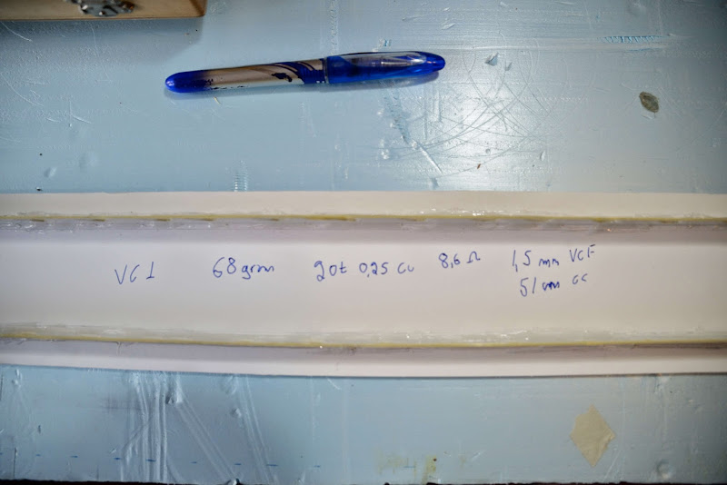
Done:
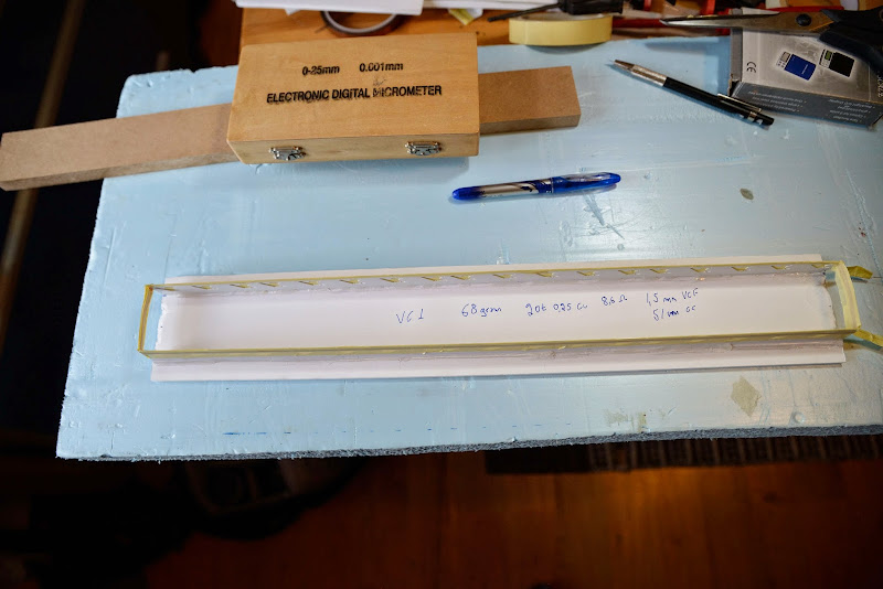
I wil have to trim the tape later:
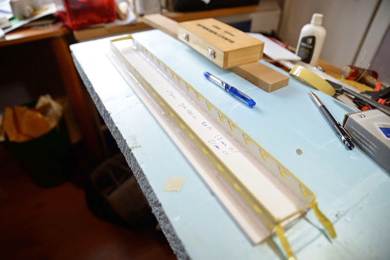
VC1 data:
First 10 turns:
Need to fixate the wire before applying the 74 film:
Next layer:
Done:
I wil have to trim the tape later:
VC1 data:
- Status
- Not open for further replies.
- Home
- Loudspeakers
- Planars & Exotics
- Yet another DIY Planar Bass