Wider membrane
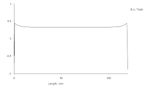
If the membrane is 190 mm wide, that is 15 mm at the top and bottom are outside the field, the 7 mm horisontal strips will be 8 mm outside the field.
Hopefully I can do the sagittal fixation here as well.
I will use kapton tape to extend the membrane outside the 160 mm wide the 3M film is.
Hopefully the tape will stay folded after the bake.
One positive thing with this is that the active membrane surface has increased by 10 %.
I dont think it is the horisontal conductors that resonates.
Maybe you could make a horisontal 30myx5-6mm ribbon one third up like this one:
![URL]](/community/proxy.php?image=http%3A%2F%2F%5BURL%3Dhttp%3A%2F%2Fimg17.imageshack.us%2Fi%2Faudaphonamthpfrontgross.jpg%2F%5D%5BIMGDEAD%5Dhttp%3A%2F%2Fimg17.imageshack.us%2Fimg17%2F566%2Faudaphonamthpfrontgross.jpg%5B%2FIMGDEAD%5D%5B%2FURL%5D&hash=8518a7bae14d0045c03f44f078799f8b)
Or make the pleats 6-7mm deep.
Or both
Or-----
Bernt
Maybe you could make a horisontal 30myx5-6mm ribbon one third up like this one:
Or make the pleats 6-7mm deep.
Or both
Or-----
Bernt
No, but they excites the iron bars as the membrane is fixed there.I dont think it is the horisontal conductors that resonates.
Is that for mechanical support or is the membrane divided into two circuits?Maybe you could make a horisontal 30myx5-6mm ribbon one third up
What´s the XO for this driver? Does it go as low as 150 Hz?
Then I will have to make a new folding tool or at the least re-build the one I have. I´ll test this idea with a higher membrane first.Or make the pleats 6-7mm deep.
Maybe this is what everybody else that are making AMTs discovers; too high excursion at the low end.
I think it is to break up resonances.It is only to 700hz.Is thre some sealing glue under the alu stripe?
http://www.lautsprechershop.de/index_hifi_en.htm?http://www.lautsprechershop.de/chassis/audaphon_amt_en.htm?xxx
Bernt
http://www.lautsprechershop.de/index_hifi_en.htm?http://www.lautsprechershop.de/chassis/audaphon_amt_en.htm?xxx
Bernt
Last edited:
New membrane
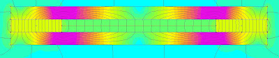
New design of the membrane with the horisontal conductors outside the magnetic flux. The membrane is now 190 mm high and shall be inserted in the 160 mm high gap. Compare to the light yellow film:

The 3m-film isn´t wide enough so some kapton tape has to cover the rest.
It is not thermo setting as the film but more robust on the other hand.
To hinder the alu-strips to fly against the film when applying it, the backside has been taped temporarily. The tape will be removed when the paper back is removed.
New design of the membrane with the horisontal conductors outside the magnetic flux. The membrane is now 190 mm high and shall be inserted in the 160 mm high gap. Compare to the light yellow film:
The 3m-film isn´t wide enough so some kapton tape has to cover the rest.
It is not thermo setting as the film but more robust on the other hand.
To hinder the alu-strips to fly against the film when applying it, the backside has been taped temporarily. The tape will be removed when the paper back is removed.
Cut out and baked:
The first and last strip was one reason for the vibrations so they have been glued to the adjacent fold.
Mounted in the motor at the terminal´s side with a L-shaped support:

The membrane now needs minimal support at the other end:

The first and last strip was one reason for the vibrations so they have been glued to the adjacent fold.
Mounted in the motor at the terminal´s side with a L-shaped support:
The membrane now needs minimal support at the other end:
Had to make some more space in the baffle:
Joyce Cooling: Revolving door. Loud and prolonged guitar notes that puts high requirements on resonance free membrane and motor.
The outermost folds still vibrates a lot, it is okay but they need to be fixed further.
Some scrap makes some vibrations, but with that gone it sounds okay; no more vibrations. Perhaps is 1 mm distance from the steel enough, next membrane will be 6-7 mm thick. But now I know that I am on the right track.
Norah Jonas: Sunrise.
Oooh, oooh.
No vibrations, that´s good!
I will assemble the other membrane before I measure and EQ.
The outermost folds still vibrates a lot, it is okay but they need to be fixed further.
In my AMTs the outmost fold conducting current are 6 mm away from the magnet. If your outmost fold are to close to the magnet I think its magnet field are disturbed by the magnet and the fold are not behaving controlled.
The outmost fold have one additional issue...
All the other folds have another fold working in a counter way, but the outmost fold will have a different air "friction" due to the next surface do not move.
Due to that the outmost folds may move erratically.
I have the outmost fold placed at 1/2 distance to the folding cassette to give it a slightly better working point - still not perfect, but better....
Yes, I observed that as well.
However, applying buds of glue from the glue gun help a little.
As you said "still not perfect, but better..."
I have no cassette for the membrane, it is glued direct in the gap at the top and bottom as you can see in post #127
I was also thinking of making the membrane completly free from the motor, then I would have to build some super structure.
With the second speaker complete, I´m in heaven.
This build has by far exceeded my expectations.
Again, thank you båndsei RayCtech and others.
On Saturday, the DIY community in Sweden has a gathering in Vänersborg and I will contribute with these AMTs.
Hopefully, more will like the design and evolve it in their own designs.
Last edited:
Measurements
Frequency response, blue 20 cm, red 100 cm:

As stated before, the lf rolloff matches my bass speakers. Only DC-protection needed at, let´s say, 50 Hz.
EQ from 2 kHz, - 6 dB/octave. Above 13 kHz I let the EQ off; the level at 20 kHz matches the one at 2 kHz.
Frequency response, blue 20 cm, red 100 cm:
As stated before, the lf rolloff matches my bass speakers. Only DC-protection needed at, let´s say, 50 Hz.
EQ from 2 kHz, - 6 dB/octave. Above 13 kHz I let the EQ off; the level at 20 kHz matches the one at 2 kHz.
Only DC-protection needed at, let´s say, 50 Hz.
Let´s make that 150 Hz. The energy at 50 to 150 Hz, although not giving a high SPL, actually burnt one of the membranes 😡
If you use a waveguide instead of EQ you will improve the fidelity as the distortion will be much lower. And the directivity and soundstage improves also...
Picture shows the first prototype with AMT "midrange" and AMT "super tweeter" in a CNCed Corian waveguide, and three 8" drivers in a combined CNCed Corian baffle / basket..
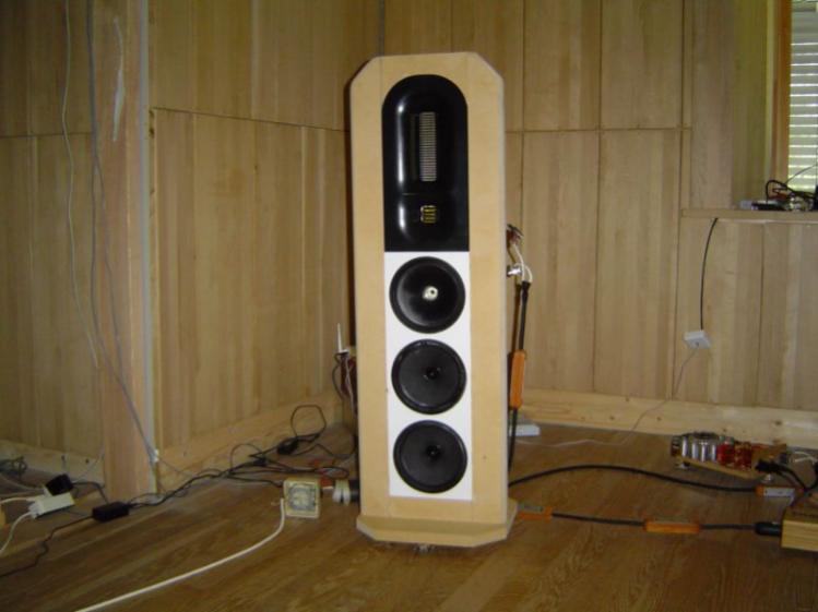
Picture shows the first prototype with AMT "midrange" and AMT "super tweeter" in a CNCed Corian waveguide, and three 8" drivers in a combined CNCed Corian baffle / basket..
The reason for the breakdown was that the kapton tape at the ends were too stiff compared to the film so that the membrane actually were torn apart at the joint.
Next membrane will have film at the ends.
Next membrane will have film at the ends.
@RayCtech: Nice setup. Waveguide, yes perhaps, but that´s a couple of steps from where I am now.
Several changes made to the membrane:
film instead of kapton tape at the top and bottom of the membrane that are outside the motor,
one fold less to get the first and last pleats out of the magnetic field´s fringe effects,
and finally using the 7 um foil.
Still some beads of glue in the outermost folds.
It really did the trick, vibrations are gone.
Played several hours with the AMTs at the Vänerborg gathering, everyone was overwhelmed by the sound quality of these AMTs.
So next step would be to do SQ measurements and perhaps do some tests with a wave guide that you mentioned, RayCtech.
Will a simple one made of a piece of 50 mm thick extruded polystyrene foam (XPS) do to start with?
So next step would be to do SQ measurements and perhaps do some tests with a wave guide that you mentioned, RayCtech.
Will a simple one made of a piece of 50 mm thick extruded polystyrene foam (XPS) do to start with?
Wave guides are an "art discipline" in itself. You will find a lot of info in this site and else on the net. The wave guides I posted a photo of are designed to be used together with the 8" drivers and the AMTs have also been designed for this. Thus the 8" voice coil are 38 mm, the AMTs width are 38 mm (the super tweeter AMT are 38 x 38 mm). The wave guide width matches the 8" outer diameter. The most important issue are the shape of the wave guide: So in my example both the wave guide and the 8" cone shapes are designed to match what I found to be the optimal shape..
So if it was a 15" I would integrate the AMTs with - then the wave guide shape formula would be the same, but the dimensions different.
But just start with a 50 mm rounded XPS - listen and measure, and compare to the original... Then you will have some data quickly and can evaluate if the "wave guide alley" are something you will use your time on
Last edited:
Thanks, RayCtech.
I´ll start on the wave guide path then with a simple rounded shape cut out from the 50 mm XPS.
To adopt the dimensions to the 15-inchers is a good start. It´ll be from 160 mm to 380 mm then; 50 mm thick and 100 mm wide more or less (160 + 100 + 100 = 360 mm).
I´ll start on the wave guide path then with a simple rounded shape cut out from the 50 mm XPS.
To adopt the dimensions to the 15-inchers is a good start. It´ll be from 160 mm to 380 mm then; 50 mm thick and 100 mm wide more or less (160 + 100 + 100 = 360 mm).
Thanks, RayCtech.
I´ll start on the wave guide path then with a simple rounded shape cut out from the 50 mm XPS.
To adopt the dimensions to the 15-inchers is a good start. It´ll be from 160 mm to 380 mm then; 50 mm thick and 100 mm wide more or less (160 + 100 + 100 = 360 mm).
Then the depth of the wave guide should match the 15" - depth from front of driver (15") to where the voice coil / dust cap are mounted. My 15" cones are 100 mm deep....
Last edited:
- Status
- Not open for further replies.
- Home
- Loudspeakers
- Planars & Exotics
- Yet another DIY AMT