Fill the empty spaces?
How can that lead to a better sound?😕
The soundwaves from the driver hits the walls of the waveguide. The walls start to resonate and sound is "trapped" in the chambers behind the walls of the waveguide. This leads to more resonances. If there were no empty spaces behind the walls this would mean it's much harder to make the walls of the waveguide resonate and therefore less ringing and so on.
It's just a theory though. I'm no master and I might very well be wrong.
Solhaga, I think he is talking about Bandsei's setup in post 154....
Correct!
Then the depth of the wave guide should match the 15" - depth from front of driver (15") to where the voice coil / dust cap are mounted. My 15" cones are 100 mm deep....
Is this because of variations of delays that will be introduced otherwise?
It is the end of the road for this membrane design.
Many measures has been taken, but there is still some vibration/resonance.
So I have to follow the main stream and mount the membrane in a frame before inserting it in the motor. The frame will be mounted from the top to make it easier if there´s a wave guide in front.
The outermost pleats will still have aluminium but not included in the circuit.
This in order to minimize the boundary effects and still start with a full pleat, :I guess you might call a suspension.
Be warned, there will be pictures along this way as well.😱
Hello, took months reading and trying to understand, I'm so not knowing english, I hope the google translator reflect what I will describe;? Graphene ò if made would improve the molybdenite is invention? I say that already manufacturing capacitors reference purposes and new batteries with graphene and apparently dramatic improvement is apparently graphene is diamagnetic and my meager apparently can increase the speed of the membranes reducing mass and weight, what are you thoughts about this idea ?
Greetings to all.
Greetings to all.
Last edited:
Currently only experimental, on this page: Supercondensadores
There are also videos on Youtube where they explain how to convert em graphene graphite oxide, and to make use a flash photograph.
There are also videos on Youtube where they explain how to convert em graphene graphite oxide, and to make use a flash photograph.
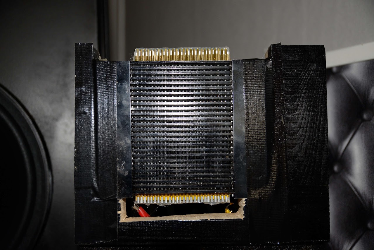
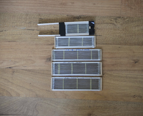
Folded and got framed
Some updates on recent events...
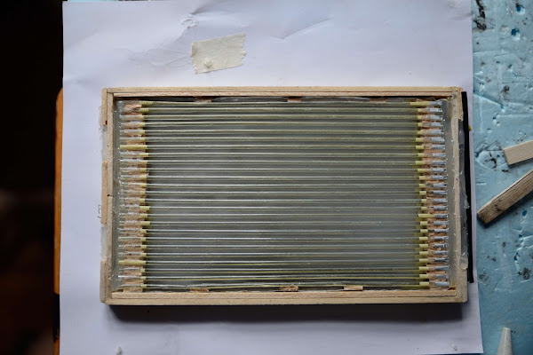
Got the membraned framed:

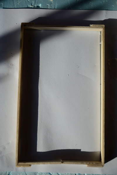
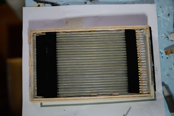
Made the ends a little stiffer:

Mounted the membrane in the frame and the frame in the motor:
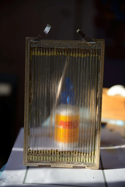
An improvement for sure. All the vibration is now on the upper and lower ends of the frame.
It almost goes away if the ends are clamped, but I suspect it is better to have a soft suspension instead; there will be more tests with frames and new membranes.
Anyway, no vibration in the iron bars themselves. That was a relief.
Some updates on recent events...
Got the membraned framed:
Made the ends a little stiffer:
Mounted the membrane in the frame and the frame in the motor:
An improvement for sure. All the vibration is now on the upper and lower ends of the frame.
It almost goes away if the ends are clamped, but I suspect it is better to have a soft suspension instead; there will be more tests with frames and new membranes.
Anyway, no vibration in the iron bars themselves. That was a relief.
Made a measurement with the frame (red) compared to my focused arrays (blue):
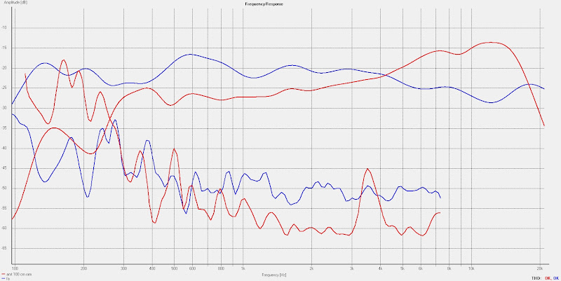
For sure something gotta be done in the lf area and there´s some nasty distortion at 3500 Hz (and 7 kHz as well of course), but otherwise, with a wave guide, it looks quite promising.
For sure something gotta be done in the lf area and there´s some nasty distortion at 3500 Hz (and 7 kHz as well of course), but otherwise, with a wave guide, it looks quite promising.
I´m trying to understand what´s limiting the lf response.
Is it the height of the membrane?
So I reduced the radiating area from 160 mm to 120 mm (membranes are horisontal in the pictures below):
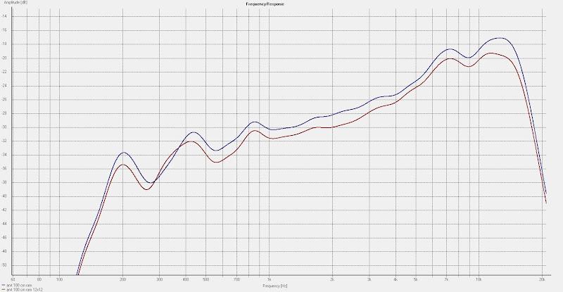
Nope, that wasn´t it (blue 160x120, red 120x120):
So I can just as well make the motor 120 mm high and thus reduce the height of the membrane to 160 mm including the horisontal intermediate traces that will be outside the motor.
I then don´t have to patch the 160 mm 3M film.
Also a waveguide would have a 120x120 mm throat instead of 120x160.
Is it the height of the membrane?
So I reduced the radiating area from 160 mm to 120 mm (membranes are horisontal in the pictures below):
Nope, that wasn´t it (blue 160x120, red 120x120):
So I can just as well make the motor 120 mm high and thus reduce the height of the membrane to 160 mm including the horisontal intermediate traces that will be outside the motor.
I then don´t have to patch the 160 mm 3M film.
Also a waveguide would have a 120x120 mm throat instead of 120x160.
Last edited:
Hi Solhaga.
I have sent you some of my leftover diaphragms.Hope it helps yoy to determine wich way to go.
As you have discovered ,length is important.dont make any shorter than 160mm,I think.
Depth ,not less than 6-7mm.
Width I am not to sure. I did not go deeper with wider than 40mm.But this could be my magnetsystem.
Number of pleats and Width of them.I use 1mm Width and 30 pleats for my 40mm diaphragm ,and that is the best I have tried.
You are welcome to post Measurements of mine diaphragms.
Bernt
Yeah, that would be really interesting. Thanks Bernt 
I don´t understand the "not shorter than 160 mm" though.
The measurement only showed a couple of dBs in SPL difference, the frequency response was the same. But I will test this more before I re-build my motor.
I will also measure this with 10 um aluminium.
I agree on the depth, 8 mm seems to work really well and that´s more than 6-7 mm. I think that I have come to terms with the vibrations as well.
Width, well any wider than 120 mm and the field gets weaker and not uniform.
I will also try 3 mm pleat width, just waiting for some 3 mm aluminium bars.
I did the same comparision as in post #175 but with a membrane with 10 um aluminium. Got almost the same result, the difference was a little less though, only 1 dB instead of 2.
Comparision between a 10 um and a 7 um aluminium thickness membrane gives that the 10 um has 6 dB higher output, mostly due to the lower impedance, but an 100 Hz higher lf response.
Roughly 300 Hz instead of the 200 Hz response the 7 um has.
All things were not equal though; the 7 um had an 160 mm high membrane and the 10 um an 140 mm high membrane.
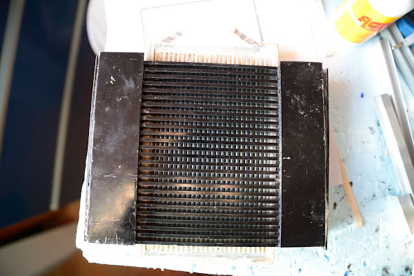
Not being satisfied with only adding tape to make the motor virtually 120 mm high, I actually removed six bars to make the motor 120 x 120 mm.
Same measurement as before, 7 um and 10 um (with 6 dB less input power):
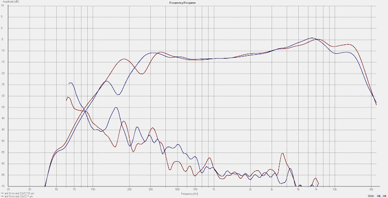
So 120x120 mm and 7 um aluminium foil it is.
I will make a wave guide before attacking the 250 Hz dip, perhaps it will be gone by then.
Same measurement as before, 7 um and 10 um (with 6 dB less input power):
So 120x120 mm and 7 um aluminium foil it is.
I will make a wave guide before attacking the 250 Hz dip, perhaps it will be gone by then.
- Status
- Not open for further replies.
- Home
- Loudspeakers
- Planars & Exotics
- Yet another DIY AMT