I went out and tried it again the morning. It didn't oscillate, and it generates a lot of power, but then the circuit breaker blew. I reset everything, and turned off my scope (which makes some noise), and noticed a slight hum from the transformer. I looked at the rails and found that they are sagging to about +/-60 volts, so something is clearly off in the output stages.
I suspect the oscillation was a transient condition while a couple of the output transistors were in the process of failing, and they have probably failed at some intermediate resistance level. The heatsinks now get quite hot, even though the putout is still cleaning swinging +/-50 volts across 8 ohms, so clearly something is drawing a lot of additional current.
I ordered a set of power transistors and will start by disassembling the outputs, and testing all the parts, replacing the transistors , etc.. If this works, this will be my premier amp, since it has a nice clean and solid control board.. and will have a fully refurbished output section.
Scott
Hi Scott,
Look at the capacitor that goes across the feedback resistor. Try reducing the value, but be very careful to use capacitors rated for 250 volts or better. The cheap ceramic capacitors are normally rated for 50 VDC only. You'll want to use NP0/C0G ceramic, polystyrene, Teflon or polypropylene capacitors for that position once you find the correct value. Polystyrene caps do not like heat from your soldering iron, so leave some lead length that you can put a clip on, or be quick with your soldering. Other than that, they are fantastic capacitors (nearly a perfect capacitor, ie very low dissipation factor).
Transistors near the point of oscillation will often break out into full blown oscillation when the current rises, increasing their bandwidth. Heat will accomplish the same thing, or turning up the bias current (guess what one test I use is?). The actual problem is in your circuit board layout, but can be compensated for. That's the reason I wanted you to make an exact copy, even though it probably didn't make sense to you at the time.
-Chris
Hi maceoc3,
NEVER DO THAT !!!
This is a perfect way to damage a previously good part and create another amplifier that has trouble (or another channel). So please, never, never swap parts around. If something does go wrong, it can create a very difficult repair job (read: more expensive).
As you gain experience in troubleshooting, you will be able to test parts without resorting to substitution. If you're going to do that, buy new parts and simply change them, discarding the ones you pulled out.
The results of the test you performed do make it seem like you have a full short across the output stage, or the catch diodes or the rectifier. Maybe allow some more current to flow so that you can have more clear test results. To isolate the output stage, pull the fuses and see if the current draw drops.
-Chris
Well, you did a lot of work there. Problem is this ...Speaking of cheating, before I saw your post I swapped the following parts from a working amp one-at-a-time:
rectifier - no change
big caps - no change
transformer - no change
NEVER DO THAT !!!
This is a perfect way to damage a previously good part and create another amplifier that has trouble (or another channel). So please, never, never swap parts around. If something does go wrong, it can create a very difficult repair job (read: more expensive).
As you gain experience in troubleshooting, you will be able to test parts without resorting to substitution. If you're going to do that, buy new parts and simply change them, discarding the ones you pulled out.
The results of the test you performed do make it seem like you have a full short across the output stage, or the catch diodes or the rectifier. Maybe allow some more current to flow so that you can have more clear test results. To isolate the output stage, pull the fuses and see if the current draw drops.
-Chris
So this must be C105...I just ordered a selection of 630 volt polypropylene caps.. so I'll try that.Hi Scott,
Transistors near the point of oscillation will often break out into full blown oscillation when the current rises, increasing their bandwidth. Heat will accomplish the same thing, or turning up the bias current (guess what one test I use is?). The actual problem is in your circuit board layout, but can be compensated for. That's the reason I wanted you to make an exact copy, even though it probably didn't make sense to you at the time.
-Chris
That said, there is now no oscillation, so I think the issue was a dying transistor..
The 3 MHz oscillation was very low level (about 20-100 mV), so I doubt that cooked the transistors. I think they were on their way out (remember one was bad from the start), and running them near full power was the nail in the coffin for them.
The control board into a resistive load is rock solid, without a hint of oscillation, so I don't think it is the layout. Other than being two-sided, the general layout of the board is similar, if not exactly the same as the original.
Hi Scott,
-Chris
But it is the reactive loads that cause marginal circuits to misbehave. When testing, you should get fairly ignorant about what you do to the poor circuit you just lovingly put together. It is the only way to ensure that it won't go out in a blaze of gory (not glory) on a new set of speakers.The control board into a resistive load is rock solid, without a hint of oscillation, so I don't think it is the layout.
But ... and this is very important ... do they fit the board?? That is actually a serious concern.I just ordered a selection of 630 volt polypropylene caps.. so I'll try that.
I would be surprised if that was the case, but stranger things have happened. You are replacing entire sets of transistors, aren't you? Never replace only some outputs in a stage that has failed. The drivers should have been changed out as well.so I think the issue was a dying transistor..
No worries, that wouldn't harm anything.The 3 MHz oscillation was very low level (about 20-100 mV), so I doubt that cooked the transistors.
Cool. I do really like the arrangement of your new PCB design. I'm hoping that you don't have a gremlin. Of everyone you know, I'm rooting for your new design the most, just so you know where I'm coming from.Other than being two-sided, the general layout of the board is similar, if not exactly the same as the original.
-Chris
Hi maceoc3,
Well, you did a lot of work there. Problem is this ...
NEVER DO THAT !!!
This is a perfect way to damage a previously good part and create another amplifier that has trouble (or another channel). So please, never, never swap parts around. If something does go wrong, it can create a very difficult repair job (read: more expensive).
As you gain experience in troubleshooting, you will be able to test parts without resorting to substitution. If you're going to do that, buy new parts and simply change them, discarding the ones you pulled out.
The results of the test you performed do make it seem like you have a full short across the output stage, or the catch diodes or the rectifier. Maybe allow some more current to flow so that you can have more clear test results. To isolate the output stage, pull the fuses and see if the current draw drops.
-Chris
Thanks Chris- I know you are right. In this case frustration + impatience = poor judgment !
The shorted behavior persists with the rail fuses out and/or with the DC leads removed from the rails. I think this is what led us to the rectifier/transformer/filter cap circuitry.
Before reading your post I convinced myself the problem with this amp must be something I had done when working on the input board so I pulled it back out (amp still shorted with no input board) to take a closer look. I have also physically removed one of the output stage/heat sink assemblies as part of a complete disassembly that had to take place in order to straighten or replace a badly bent up chassis bottom. While these are out on the bench it will be a good opportunity to check the components one-by-one especially in light of the fact these areas have not really been looked at yet.
Received the little signal generator today. Any advice on a general purpose variable DC power supply?
Hi maceoc3,
Yes, it looks like your problem is in the main power supply. That's rare.
I buy my power supplies used, but I normally buy HP/Agilent/Keysight equipment for low voltage (or HV if I see one) stuff, and old Heathkit or Lambda power supplies for higher voltage supplies. Sure they often need fixing when you get them, but they are great quality and last after they are fixed. For 12 VDC supplies, I look for older stereo board display power supplies. 24 / 28 VDC supplies are easy to find in industrial salvage.
The only off-shore supply I ever bought has been completely rebuilt and redesigned. All that's original are the case, transformer and PCB. It kept blowing when used within its ratings. Go over and it was broke again for sure.
-Chris
I have a BK supply that goes to 30 volts and has fixed 12 and 5 volt apply outputs.
It is very rugged and quite useful, but I wish it had plus and minus variable outputs..
So, it I were buying a new supply, I'd get a dual polarity unit. maybe like this:
http://www.ebay.com/itm/Agilent-HP-...401833?hash=item3f64855ee9:g:UKcAAOSwbYZXWcBM
It is very rugged and quite useful, but I wish it had plus and minus variable outputs..
So, it I were buying a new supply, I'd get a dual polarity unit. maybe like this:
http://www.ebay.com/itm/Agilent-HP-...401833?hash=item3f64855ee9:g:UKcAAOSwbYZXWcBM
Last edited:
That's a nice supply.
HP power supplies tend to be very low noise. That is one reason they tend to be pricey.
I got an older 6255A, which is two supplies up to 40 VDC (50 actually) at 1.5 amperes. You can strap it for tracking, so one tracks the other. Something I need to do with mine. These are rack mount, and can be found on Ebay fairly often. You can set a current limit too.
-Chris
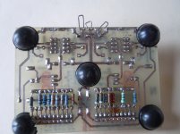
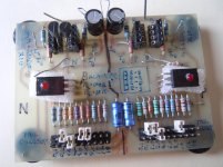
I pulled off the output stages from the #4 amp today, and did some measuring. I found one transistor that had a base to collector short. Interestingly, this didn't keep the amp from working, but it definitely made it draw lots of power. If you consider it, the base/collector short would have biased all of the transistors on (although not fully on) continuously. That would mean that during the opposing half cycle, the other output bank would be on, and the amp would be sort of operating in Class A..drawing current directly through both banks on each half cycle. It is impressive that the servo was able to keep the output balanced even under this situation. Obviously, had this been a collector emitter short it would have popped a fuse, but being a "softer" failure, it merely draws lots of AC current that popped the smaller circuit breaker on my power strip.
I ordered a full set of output transistors and will put those in when they arrive.
S
I ordered a full set of output transistors and will put those in when they arrive.
S
Hi Scott,
Actually, collector to base leakage is sometimes a "soft" failure mode, but a short is exactly like emitter collector shorts except that it involves the entire bank as you've noted. There is nothing soft about that failure mode. I guess there is a first for everything.
-Chris
Actually, collector to base leakage is sometimes a "soft" failure mode, but a short is exactly like emitter collector shorts except that it involves the entire bank as you've noted. There is nothing soft about that failure mode. I guess there is a first for everything.
-Chris
Chris, Scott
Currently bidding on an HP-E3616A, wish me luck!
Chris,
Would you mind posting the layout of your transistor matching jig? I've found many references to it, but can't seem to find the actual diagram in decent enough resolution for printing.
maceo
Currently bidding on an HP-E3616A, wish me luck!
Chris,
Would you mind posting the layout of your transistor matching jig? I've found many references to it, but can't seem to find the actual diagram in decent enough resolution for printing.
maceo
Hi Scott,
Actually, collector to base leakage is sometimes a "soft" failure mode, but a short is exactly like emitter collector shorts except that it involves the entire bank as you've noted. There is nothing soft about that failure mode. I guess there is a first for everything.
-Chris
Yeah, what I meant by a "soft' failure is that it was not a dead short, sand the amp still worked.. but it is not something one could live with for long.
Another observation is that the failed transistor is one from the same bank (the negative side set) that had a failure earlier. I had, against your advice, replaced just the one failed device. I am sure the others were stressed in various ways from the other failure, and once I got the amp running, the next one failed..
Scott
Chris, Scott
Currently bidding on an HP-E3616A, wish me luck!
Chris,
Would you mind posting the layout of your transistor matching jig? I've found many references to it, but can't seem to find the actual diagram in decent enough resolution for printing.
maceo
esnipe.com is your friend....Lets you bid in absentia, and hides your bid until about 6 seconds before the end of the auction (to avoid bidding wars).
Hi maceo,
Good luck!!!
I hope you get it, and I hope its working properly.
I've attached a few things for you. The schematic was done with DipTrace, which is a free to use limited program. I can recommend it. You should be able to print from the PDF file. Oh, I see it didn't upload the schematic file. I'm going to change the file type to B Matcher.PDF, change it back to B Matcher.sch.
Once I get it all written up, the design was given to DIYAudio. Hopefully then it will be in the store. One nice feature it has is that the tail current is setable.
If you look in the picture, you will notice the pass transistors are sitting on foam. That 3 mm red LED is sitting through the hole in the transistor with surrounding air blocked so it is more stable with temperature. So the foam is necessary for better stability. It will work without it.
Sockets. Don't buy the cheap Chinese ones, stick with US manufactured stuff. I bought some to try, and they are not good at all. They come in strips that you separate in the lengths you need. There are four places so that all common transistor pin-outs are covered. You can see the resistors underneath that I padded the current levels to be more exact. You don't have to do that, I was experimenting.
-Chris
March 2019, added the two files in Zip format. The files inside are for DipTrace. I highly recommend it.
Attachments

Chris,
Thanks so much for posting this!! I'm not having any luck opening the schematic file in DipTrace. Looks like DipTrace uses a .dch file extension. I have tried .sch and .dch without any success.
Thanks so much for posting this!! I'm not having any luck opening the schematic file in DipTrace. Looks like DipTrace uses a .dch file extension. I have tried .sch and .dch without any success.
Chris;
I have been replacing the output transistors in my #4 amp.
I decided to check all the resistor values while I had the output blocks out.
I had two open 10 Ohm resistors in the negative block (the one that had two bad transistors), and the 5 watt ceramics in that block all measure about 0.5 ohms in situ (one was open).
The positive side has no open resistors, but I found that the 5 watt units measure between 0.4 and 0.6 Ohms.
The schematic shows these as 0.33 ohm devices. Should I replace them all?
Seems like they should at least be all the same...
Thanks
Scott
Hi Scott,
Just recheck your ohmmeter, just to make sure leads and everything are good and it isn't lying to you. For resistors, replace all that have readings beyond their stated values. You don't have to replace all. Also inspect the bodies of the smaller resistors and replace any that have discoloration.
Some resistors drop in value before they shoot up towards being open. So if a resistor measures out of tolerance low, replace it as well. Do not forget tot compensate (or null out) the resistance from your leads, especially when measuring low resistances. If your meter will do Kelvin (4 -wire) measurements, use that mode. The meter would have 4 jacks in that case, and probably be a bench meter.
Hi maceoc3,
Have you renamed "B Matcher.PDF" to "B Matcher.sch"? You may have to add a bunch of libraries in order for the program to be able to display that file.
-Chris
Chris,
Yes, I have renamed the file with the .sch file extension though it should be noted the DipTrace PCB Layout program is looking for a file extension of .dch or .dip and the DipTrace Schematic program is also looking for a .dch file extension. I have tried all of these and in each case the error message indicates the file is not of the proper format.
Yes, I have renamed the file with the .sch file extension though it should be noted the DipTrace PCB Layout program is looking for a file extension of .dch or .dip and the DipTrace Schematic program is also looking for a .dch file extension. I have tried all of these and in each case the error message indicates the file is not of the proper format.
- Home
- Amplifiers
- Solid State
- Yet Another Adcom GFA-565 Thread