Sounds about what I got on my third try. Still would take you down to the hundreds of hertz.
Bummer !!!!
Power supply filtering I think.
Shoog
Bummer !!!!
Power supply filtering I think.
Shoog
If this 12B4a preamp was hooked up to a current output DAC (like Monica2), will it work well? I read somewhere that this type of DAC prefers a lower input impedance, like the GG design? So I need a I/V resistor that will solve the problem?
thanks!
thanks!
Shoog said:Just a simple question. I am toying with the idea of building a 12B4 preamp. I have some big light ballast tranformers which I would like to try as plate chokes. I expect them to be good down to at least 400hz. The question is could I put a simple single transistor CCS before the choke (ie +B - CCS - CHOKE - PLATE) to take up the slack.
Shoog
Uhhh,
What do you think what’s left from the inductance when biased with the DC anode current? These ballasts are not designed for DC bias and probably driven into saturation right away.
Cheers 😉
If this 12B4a preamp was hooked up to a current output DAC (like Monica2), will it work well?
You need a voltage output type DAC and then it'll work fine. HGo back and look for BRian BEck's schematic in this thread. Thats exactly what he's using this line stage for!!
Mark
4 channel Pre
Hi
I'm thinking of making a 4 channel preamp after my behringer dcx 2496. I have baypassed the analog section like this:
As it is now, i run the signal directly into my 6 deck pot(I use only 4), and directly to each amp. The pot is 20k.
Would the 12B4 circuit have any problems matching the DACs (AKM 4393) output? Shold the pot be placed before or after the 12B4?
Cheers
bjorn
Hi
I'm thinking of making a 4 channel preamp after my behringer dcx 2496. I have baypassed the analog section like this:
An externally hosted image should be here but it was not working when we last tested it.
As it is now, i run the signal directly into my 6 deck pot(I use only 4), and directly to each amp. The pot is 20k.
Would the 12B4 circuit have any problems matching the DACs (AKM 4393) output? Shold the pot be placed before or after the 12B4?
Cheers
bjorn
Mark A. Gulbrandsen said:
You need a voltage output type DAC and then it'll work fine. HGo back and look for BRian BEck's schematic in this thread. Thats exactly what he's using this line stage for!!
Mark
Ok, gotcha.
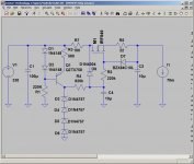
Brian,
Can you show me how do you compute the values of R10, R21, L1 and C3? Would this values be applicable to Monica2?
thanks! 🙂
Single or dual CCS?
Hello,
My first time posting although have been reading for a while. I am building a 12b4 pre. Does anyone know if when using a CCS at the cathode it is best to have be one CCS for each tube or just one shared CCS for both tubes?
Tom
Hello,
My first time posting although have been reading for a while. I am building a 12b4 pre. Does anyone know if when using a CCS at the cathode it is best to have be one CCS for each tube or just one shared CCS for both tubes?
Tom
Hey,
Mark, you haved try the RNT-400 from thiel in combination with a DC load from your powersupply, can I see 🙂
Have you try it with a 220Vac load?
I wonder if the noise floor is still low, if it would be an option for me as a supply on my 12b4a preamp.
Venlig hilsen Jan Jensen
Mark, you haved try the RNT-400 from thiel in combination with a DC load from your powersupply, can I see 🙂
Have you try it with a 220Vac load?
I wonder if the noise floor is still low, if it would be an option for me as a supply on my 12b4a preamp.
Venlig hilsen Jan Jensen
Mark-there it is
OK Choky,
I hook up your gas tube regulator diagram and nothing happens....the glow tubes don't glow.... or shall we say there is no ignition.... any idea what might be wrong?
Thanks!
Mark
Re: Single or dual CCS?
HI BGcap
Welcome! You must use one CCS for each cathode. Circuits with two cathodes sharing one CCS have an other function, namely phase inversion to drive PP stages.
Erik
BGcap said:Hello,
My first time posting although have been reading for a while. I am building a 12b4 pre. Does anyone know if when using a CCS at the cathode it is best to have be one CCS for each tube or just one shared CCS for both tubes?
Tom
HI BGcap
Welcome! You must use one CCS for each cathode. Circuits with two cathodes sharing one CCS have an other function, namely phase inversion to drive PP stages.
Erik
Update!
I got it working on just one channel tonight but I did get them glowing. I need to get different resistors tommrrow at the parts store. Note the wrong basing at this site This was my problem. Should have been labeled pin 5.... not pin 4... there is not even a 4th pin on these tubes bases....
I got it working on just one channel tonight but I did get them glowing. I need to get different resistors tommrrow at the parts store. Note the wrong basing at this site This was my problem. Should have been labeled pin 5.... not pin 4... there is not even a 4th pin on these tubes bases....
Mark A. Gulbrandsen said:Update!
I got it working on just one channel tonight but I did get them glowing. I need to get different resistors tommrrow at the parts store. Note the wrong basing at this site This was my problem. Should have been labeled pin 5.... not pin 4... there is not even a 4th pin on these tubes bases....
yup; wrong pinout
just go to Duncan's and download tdslpe..........
if you didn't already........
did you listen that solo channel?

Attachments
Mark A. Gulbrandsen said:
OK Choky,
.... any idea what might be wrong?
Mark
hehe
I have idea-certainly lack of jfets in circ to give that spark for ignition.....
just imagine what jfet will do on 100+ volts........
I saw some schematics here that use capacitor input and some choke input. For this particular tube (12B4), I'd like to hear the experiences and opinions as to the differences between these 2. I'm in the process of plannign a simple 12B4 preamp and am deciding on the secondary voltage of the power transformer. I already have a 5H 150mA (DCR <100ohms) choke from a previous project to use, and a 15uf motor run, and various 'lytics that I can use. I will be driving a EL84 PP with it, and will probably go with the LM317 on the cathode.
Pls advice, thanks! 🙂
Pls advice, thanks! 🙂
pengboon, i'm not sure if you were able to see the progression of my 12B4 which started with cap input and then fdegrove suggested the modifications (not more cap input) and to my ears there's no difference at all.
the audible difference is when I changed to MOSFET PSU and finally LM317 on the cathode.
the audible difference is when I changed to MOSFET PSU and finally LM317 on the cathode.

Thanks Arnoldc for your inputs. This thread has gotten very long, and when I searched, it doesn't tell me the page where the search string is found, so it's pretty tedious to go through all the pages...  Is your PSU on post #230?
another thing, can I actually use this as a headphone amp as well, what modifications do I require to make this happen?
thanks!
Is your PSU on post #230?another thing, can I actually use this as a headphone amp as well, what modifications do I require to make this happen?
thanks!
Erik,
Thanks for the help. I will follow your advice. I hope to have my first 12b4 pre done soon. This is the regulator I plan to use:
http://www.antiquewireless.org/otb/resto0504.htm
Any comments?
Tom
Thanks for the help. I will follow your advice. I hope to have my first 12b4 pre done soon. This is the regulator I plan to use:
http://www.antiquewireless.org/otb/resto0504.htm
Any comments?
Tom
arnoldc said:
adjust the zener string for the proper output voltage.
Your input to this is after rectifier or after rectifier-C-R-C-R-C? So add zeners to raise the final output voltage? Can the caps by lytics, your diagram seems to show poly?
thanks for your help!
- Home
- Amplifiers
- Tubes / Valves
- Yet another 12B4 line stage, or is the 12B4 better than the Grounded Grid.....