Brian,
I enjoy your posts and hope you are feeling a whole lot better after a good vomit and scratch (sounds just like my cats - I sincerely hope you don't have furballs or fleas) . However, I must admit to having a good scratch myself (on my scalp of course) after digesting your rant-de-force.
You state:
Sorry, but I fail to see the analogy - I think the comparison made was between a bypassed LM317 on the cathode and an entirely different type of CCS (Gary Pimm CCS or cascoded 10M45S were mentioned in my post) on the plate: not a comparison of an LM317 CCS applied in the two differing locations. if I misunderstood and the term CCS was being used generically, I disagree and think the comparison (based on sonic outcome) is entirely valid. No problem, I prefer my cheese bent anyway.
Your circumnavigation of all things CCS contained an interesting blend of technical fact and personal opinion (which to your credit was usually identified as such) but I must admit that I failed to see the real point of the whole journey😕. Pissed at being dissed perhaps, because somebody prefers something different to your favourite topology?
Interestingly, within your exposition of the virtues of the bypassed 317 you credit Gary's 'uberCCS' (and only Gary's!), which I use and compared to the 317, as having potential to actually sound ok. (I certainly would not disagree with your argument that shunt capacitance and its variability, rather than dynamic impedance, is probably the key determinant of sound quality). For interests sake, Gary's measurements are reproduced below:
Fixture limit .009pf
2G test resistor .159pf
Supertex cascode DN2540 .177pf
IXYS 10M45 2.248pf
Single IRF820 4.426pf
Single Supertex DN2540 32.4pf
Check out the capacitance of a single 10M45S. I figure a cascoded pair must be getting down pretty low as far as CCS' go...
But the bit in your post I really don't get is the claim that the possible improvements you describe would entail ' a giant leap up the ladder of complexity and cost'.😕
If you want a taste of choke loaded sound get a couple of H3007 from handmade at $20 ea (60H, 30mA at around 350R). If you a have real bee up your a$%! about shunt capacitance, wire two in series in a humbucking arrangement and you have pretty effective and cheap plate load. Not boutique a la MQ, but still pretty good. As for Gary's 'uber CCs' being complex and/or costly - in the overall scheme of things this is hardly a complex circuit; and how much exactly do a couple of IRF820 and LND150 with a few resistors and caps thrown in cost ? Probably less than a pair of Black Gate FX bypass caps on the 317s. If you need a really simple CCS and come out in hives at the mention of a 10M45S the solution can be as easy as using a cascoded DN2540 ($1.60 x 2) a la SY. There are lots of easily constructed and affordable alternatives.
bemused
pm
BTW I finally located a SP14 article (p16) by Herb Reichart relating to plate resistor values in which you expressed interest. Zen mod and Arnold may also find it interesting. It states:
Resistors dramatically effect (sic) tone character and resolution. The worst offenders are high value plate load and cathode resistors. This is not simply an issue of metal film v carbon composition. It is the value! Using plate resistors of greater than 2xRp, despite issues of measured THD, make triode stages generalize and sound rough and jumpy. The trick is to reduce the value of plate resistance to the point where the transconductance (and probably THD) are maximized and then reduce it a touch further.
For the opposition viewpoint I refer you to this link http://www.htg2.net/index.php?topic=9548.msg77605
where Thai DIYers are building triode strapped pentode (6CW4, 6BQ5, E80L) linestages with 100k !!! plate resistors and very low current. It must be a popular design because it appears they have a group buy PC for the project. If anyone can read Thai I would love a translation.
I enjoy your posts and hope you are feeling a whole lot better after a good vomit and scratch (sounds just like my cats - I sincerely hope you don't have furballs or fleas)
. However, I must admit to having a good scratch myself (on my scalp of course) after digesting your rant-de-force. You state:
When I hear some folks debating using a CCS as a plate load or as a bypassed cathode bias device, I have to scratch a body part. That’s like debating whether cotton is best used in pillow cases or gym socks. Apples and oranges. Cheese straighteners and door knobs.
Sorry, but I fail to see the analogy - I think the comparison made was between a bypassed LM317 on the cathode and an entirely different type of CCS (Gary Pimm CCS or cascoded 10M45S were mentioned in my post) on the plate: not a comparison of an LM317 CCS applied in the two differing locations. if I misunderstood and the term CCS was being used generically, I disagree and think the comparison (based on sonic outcome) is entirely valid. No problem, I prefer my cheese bent anyway.
Your circumnavigation of all things CCS contained an interesting blend of technical fact and personal opinion (which to your credit was usually identified as such) but I must admit that I failed to see the real point of the whole journey😕. Pissed at being dissed perhaps, because somebody prefers something different to your favourite topology?
Interestingly, within your exposition of the virtues of the bypassed 317 you credit Gary's 'uberCCS' (and only Gary's!), which I use and compared to the 317, as having potential to actually sound ok. (I certainly would not disagree with your argument that shunt capacitance and its variability, rather than dynamic impedance, is probably the key determinant of sound quality). For interests sake, Gary's measurements are reproduced below:
Fixture limit .009pf
2G test resistor .159pf
Supertex cascode DN2540 .177pf
IXYS 10M45 2.248pf
Single IRF820 4.426pf
Single Supertex DN2540 32.4pf
Check out the capacitance of a single 10M45S. I figure a cascoded pair must be getting down pretty low as far as CCS' go...
But the bit in your post I really don't get is the claim that the possible improvements you describe would entail ' a giant leap up the ladder of complexity and cost'.😕
If you want a taste of choke loaded sound get a couple of H3007 from handmade at $20 ea (60H, 30mA at around 350R). If you a have real bee up your a$%! about shunt capacitance, wire two in series in a humbucking arrangement and you have pretty effective and cheap plate load. Not boutique a la MQ, but still pretty good. As for Gary's 'uber CCs' being complex and/or costly - in the overall scheme of things this is hardly a complex circuit; and how much exactly do a couple of IRF820 and LND150 with a few resistors and caps thrown in cost ? Probably less than a pair of Black Gate FX bypass caps on the 317s. If you need a really simple CCS and come out in hives at the mention of a 10M45S the solution can be as easy as using a cascoded DN2540 ($1.60 x 2) a la SY. There are lots of easily constructed and affordable alternatives.
bemused
pm
BTW I finally located a SP14 article (p16) by Herb Reichart relating to plate resistor values in which you expressed interest. Zen mod and Arnold may also find it interesting. It states:
Resistors dramatically effect (sic) tone character and resolution. The worst offenders are high value plate load and cathode resistors. This is not simply an issue of metal film v carbon composition. It is the value! Using plate resistors of greater than 2xRp, despite issues of measured THD, make triode stages generalize and sound rough and jumpy. The trick is to reduce the value of plate resistance to the point where the transconductance (and probably THD) are maximized and then reduce it a touch further.
For the opposition viewpoint I refer you to this link http://www.htg2.net/index.php?topic=9548.msg77605
where Thai DIYers are building triode strapped pentode (6CW4, 6BQ5, E80L) linestages with 100k !!! plate resistors and very low current. It must be a popular design because it appears they have a group buy PC for the project. If anyone can read Thai I would love a translation.
I'll bet it's not the value of those resistors that makes them critical but rather the voltage across them. High value resistors tend to have high voltages, so excess noise and voltage coefficient of resistance come into play.
I donno about you guys but I've had enough of mach-1's bs. I f he continues to be uncivilized in the manner above then I ask that he at least be sin-binned or better yet banned from this forum all together. His childish displays of rudness only goes to show that he still hasn't learned that its all about sound and not about specs, iron, capacitance or other trivially stupid matters.
Mark
Mark
mach1 said:to this link http://www.htg2.net/index.php?topic=9548.msg77605
where Thai DIYers are building triode strapped pentode (6CW4, 6BQ5, E80L) linestages with 100k !!! plate resistors and very low current.
I'm in the process of lashing up a 6c45 with in-the-range-of a 1 meg plate resistor running ~1 ma off the same supply as an 813, or around 900 volts. Following it is an ..ahem.. cathode follower so it's close to unloaded. Sims promise interesting results, in the range of ~0.1% 2nd slightly over 3rd harmonic at 200 volts p-p. Worth a shot.
Sorry Mark,
It appears that you have everthing in this world figured out, and that anyone who thinks differently or expresses an alternative viewpoint either has a defective system or is mentally deranged and should be banished to the nether regions.
You say
If you actually read Brian's posts you will see that he refers a lot to specs, capacitance and other matters you may consider 'trivially stupid', but others may not.
As I have posted previously, yes it's all about the sound, but the problem is you are apparently the sole arbiter of the sound we should all aspire to.
It also seems that you are an pathetically humourless individual.
I suggest you put your dummy back in your mouth and have a good lie down.
It appears that you have everthing in this world figured out, and that anyone who thinks differently or expresses an alternative viewpoint either has a defective system or is mentally deranged and should be banished to the nether regions.
You say
he still hasn't learned that its all about sound and not about specs, iron, capacitance or other trivially stupid matters.
If you actually read Brian's posts you will see that he refers a lot to specs, capacitance and other matters you may consider 'trivially stupid', but others may not.
As I have posted previously, yes it's all about the sound, but the problem is you are apparently the sole arbiter of the sound we should all aspire to.
It also seems that you are an pathetically humourless individual.
I suggest you put your dummy back in your mouth and have a good lie down.
rdf,
Very interesting - I have never heard of anyone running a 6C45 anywhere near there. Please post on the sound when you build the circuit.
I assume those Thai linestages must perform pretty well as a lot of people appear to have built them. I just wish someone could translate the entire thread.
regards
pm
 Mark and mach, cool it. Keep to the topic and cease/desist from the personal stuff. No further warnings.
Mach1,
I appreciate your response. My post-midnight rant did have an edge, rather like inferior CCSs can have.
Hey, occasionally it’s fun to “stick the pig” and liven things up, while hopefully not getting personal about it.
To my ears, there are generally consistent differences in sound character and quality between tubes and transistors. Adding a solid-state CCS to the sensitive plate circuit truly puts it into full play with the audio signal, for better or for worse. We should be surprised if we didn’t hear any differences here. If you agree, and I think you do, then we should also agree that there has to be a reason why there are differences. I offered my ideas on possible underlying mechanisms and derivative design implications; other opinions are encouraged.
My main point was that for many DIYers wanting a simple and decent sounding line stage without a lot of fuss or risk, the wirewound plate resistor for this 12B4A design is a really safe best, and not so easy to beat (when RL/rp = 6 or more). Different CCSs as plate loads can vary greatly in performance and sound quality. The ne plus ultra 12B4A variant would probably have either a decent choke or a well-conceived CCS as a plate load. You refer to some of the potentially better ones. Perhaps I overstated the need for full turbocharging a la Pimm. There are surely other worthy candidates. It’s just that it’s SO easy to get it wrong, and to fall way short of beating the quality of a simple wirewound resistor. Then too, the more complex CCSs using faster parts may be more prone to oscillation (layout differences, etc.) that could indeed impose a step or two up the ladder of difficulty for some DIYers. I’m certainly not trying to discourage 12B4A elaborations out of any pride of ownership. This design isn’t even my “favorite topology”, to use your words. I’m putting the finishing touches a rather elaborate 6SN7 design for my main line stage. Maybe someday I’ll let it out of the box. But the simple 12B4A stage stands out in my memory as a reference point of remarkable sound quality achieved rather easily, using parts that fell right out of my parts bin, including even those big composite cathode caps.
As to Herb Reichert’s quotes, what can I say? Different strokes… Ditto for the starve-a-pentode crowd.
PS: Hey, you and Mark had better watch out! I hear that SY loves stroking his badge and has a nervous trigger finger. I steer well clear of him when he starts smacking his night stick on his palm. I’d hate to see you guys get sin-binned. Remember, this is just a hobby for most of us. If we stand back for perspective, we all share interests that have much more in common than not.
I cannot argue against the goal of the CCS in the cathode- utter simplicity and control.
I changed my cathode sink from 317 to resistor and LED stack and the former two can't give me the balance that the LM317 can give.
I'm going to put back the LM317 with more black gates this time 😀
I changed my cathode sink from 317 to resistor and LED stack and the former two can't give me the balance that the LM317 can give.
I'm going to put back the LM317 with more black gates this time 😀
arnoldc said:
I changed my cathode sink from 317 to resistor and LED stack and the former two can't give me the balance that the LM317 can give.
Arnold, how different are the LED vs LM317 sonically to you? I tried both and can't really decide between the 2 still...
p.s. which BG did you use? the NX 220u 16V?
HI
Can somebody let me know the voltage of the bypass capacitor on the LM317 .
Please , I collect the parts now and it would be great if I know what I looking for . If is a low voltage may be I'l go with BG .
Thanks
Regards
Can somebody let me know the voltage of the bypass capacitor on the LM317 .
Please , I collect the parts now and it would be great if I know what I looking for . If is a low voltage may be I'l go with BG .
Thanks
Regards
pengboon, gaborbela, I'm using 16V black gate because my bias voltage is low ~9V.
pengboon, between LED and LM317, I'd pick the LM317 by virtue of balanced voltage on the cathode. Hard to pick LEDs (read: I'm lazy) that will give me balanced voltage.
pengboon, between LED and LM317, I'd pick the LM317 by virtue of balanced voltage on the cathode. Hard to pick LEDs (read: I'm lazy) that will give me balanced voltage.
BGcap said:Would someone verify my math and topology, please? I have read and re-read the info in this thread, but want to be sure since power supplies have a tendency to melt down if something is wrong. Thanks
You'd have about 50mA max current, which should be fine, as long as your preamp draws about 20-30mA per channel.
Sheldon
BGcap said:Would someone verify my math and topology, please? I have read and re-read the info in this thread, but want to be sure since power supplies have a tendency to melt down if something is wrong. Thanks
read again my posts regarding gas toob reg,and why I choose resistor value I choose;
what is exact current through one 12B4 in your preamp?
Thanks to Sheldon and Zen Mod for the quick answers.
I have one more and also wanted to show my math work and provide some background info I left out before...
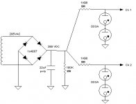
My tranny's current limit is 135mA. I am using the component values from Brian Beck's design.
This is how I did the math.
Each channel draws 29ma current: 1.25/43ohms=29mA rounded to 30mA
Desired current for each VR-150 stack: 40+5/2=22.5mA rounded to 20mA
Dropping resistor:
Src voltage - Reg voltage / VR-150 mean current + load current
399 - 300 / 20 + 30 = 99 / 50 = 1.98 or 1K980 rounded to 2k
Here's the main question I can't seem to find the answer to.
Are two dropping resistors needed, or will just one suffice? It seems like using two, effecitively in parallel would cut this resistance in half, causing bad things to happen to the gas tubes.
Should it be:
______od3stack__channel1
/
rectifier---filter---dropping resistor
\______od3stack__channel2
OR
___dropping resistor__od3stack__channel1
/
rectifier---filter
\___dropping resistor__od3stack__channel2
????
I have one more and also wanted to show my math work and provide some background info I left out before...
My tranny's current limit is 135mA. I am using the component values from Brian Beck's design.
This is how I did the math.
Each channel draws 29ma current: 1.25/43ohms=29mA rounded to 30mA
Desired current for each VR-150 stack: 40+5/2=22.5mA rounded to 20mA
Dropping resistor:
Src voltage - Reg voltage / VR-150 mean current + load current
399 - 300 / 20 + 30 = 99 / 50 = 1.98 or 1K980 rounded to 2k
Here's the main question I can't seem to find the answer to.
Are two dropping resistors needed, or will just one suffice? It seems like using two, effecitively in parallel would cut this resistance in half, causing bad things to happen to the gas tubes.
Should it be:
______od3stack__channel1
/
rectifier---filter---dropping resistor
\______od3stack__channel2
OR
___dropping resistor__od3stack__channel1
/
rectifier---filter
\___dropping resistor__od3stack__channel2
????
You should do it the way you've drawn it. Your resistors are only "effectively parallel" with respect to the power feeding them. They are independent as far as the regulator tubes are concerned. If you use a single limiting resistor it will drop 100V at 50mA current. If one side shuts down, the other side will take the full current and your reg. tubes on that side will eventually toast. As you have it drawn, if one side is off, the other side is largely unaffected (only affected by the modest raise in voltage before the resistor due to the lower load on the transformer), and will be safe.
Sheldon
Sheldon
Sheldon is correct! Do it as drawn... I did mine exactly the same way but can't vouch for the correct part values without going back to look at mine.
My pre-regulated supply is 400 volts even and my total current draw is about 110ma. Also you will notice a bit of dofference between 0D3's as far as tolerance. Try swapping them aound till you end up with almost the same B+ operating both channels.
Mark
My pre-regulated supply is 400 volts even and my total current draw is about 110ma. Also you will notice a bit of dofference between 0D3's as far as tolerance. Try swapping them aound till you end up with almost the same B+ operating both channels.
Mark
Mark A. Gulbrandsen said:Sheldon is correct! Do it as drawn... I did mine exactly the same way but can't vouch for the correct part values without going back to look at mine.
My pre-regulated supply is 400 volts even and my total current draw is about 110ma. Also you will notice a bit of dofference between 0D3's as far as tolerance. Try swapping them aound till you end up with almost the same B+ operating both channels.
Mark
Will using VR tubes, and dropping a decent amount of volts (as shown) offer better ripple control, than a conventional CRC or CLC filter?
Probably not since it is not a multiplier like a simple pass transistor is. B+ comming in needs to be very clean to begin with.
Mark
Mark
- Home
- Amplifiers
- Tubes / Valves
- Yet another 12B4 line stage, or is the 12B4 better than the Grounded Grid.....