Last month at the Burning Amp Festival, I presented a little PCB called BJT Simple Matcher. That BAF talk, plus some photos, the matcher schematic, and the PCB Gerber file, are available on the diyAudio Forum (here). At the very end of the talk, I showed a little example circuit which greatly benefits from BJT matching, named "Yes It Can Drive an F4" (revision A).
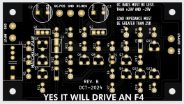
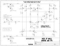
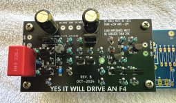
A couple of small tweaks later the newest release (rev B), which I hope is the final release, is presented here in this thread. You can see a top view of its unpopulated PCB, and also the circuit schematic diagram, in the attachments below.
WHAT IS F4 AND WHY DO I MENTION IT HERE?
F4 is one of Nelson Pass's many FirstWatt amplifiers (link). Unusually, the F4's circuitry is arranged as a Unity Gain Buffer: although F4 provides enormous current gain, its voltage gain is only 1X. To get the maximum available output, 20V (peak), you must supply an input of 20V (peak). A large number of DACs, streaming devices, smart phones, and linestages are unable to swing their outputs to 20V (peak), so these are not a good match for the FirstWatt F4.
In fact, it is so rare to encounter a line level device which CAN swing its outputs to 20V (peak), that a snarky catch phrase has arisen here on diyAudio:
I'm pleased to report that the little example circuit presented here, gives an affirmative answer. Yes it can drive an F4. Yes it can swing its output to ±20V (peak).
The board is designed to be installed within an F4 chassis and to use the existing F4 DC rail voltages, with NO modifications of the F4 power supply or the F4 amp channel. Just bolt in the new boards, one per channel, and wire them up. Done.
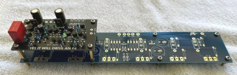
DOUBLE DECKER / PIGGY BACK MOUNTING OPTION
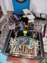
This circuit board is 50mm X 90mm; its mounting holes are 40mm X 80mm. Which is a perfect match to the left hand (or right hand) set of four mounting holes on the F4 PCB: 40mm X 80mm. Using spacers, you can mount it directly atop an existing F4 PCB, in Piggy Back (Double Decker) fashion. Please see the attached photographs.
An F4 amplifier channel board (blue PCB) has a Yes It Can Drive An F4 (black PCB) mounted directly above. The spacers in this picture are 20mm tall (M3 female, hex body, M3 male) but Amazon also sells 25mm tall spacers if you prefer longer. The male ends of the spacers replace the M3 screws which secure the F4 amp channel to its heatsink.
Of course, builders are free to mount their Yes It Can Drive An F4 boards wherever they wish, in whatever orientation they like; there's certainly no requirement to use the piggy back mounting scheme.
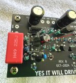
YOU CAN ZIP-TIE Q5 AND Q9 FOR BEST THERMAL CONTACT
I've arranged the PCB footprints of the matched pair Q5-Q9, so you can zip tie them together (face to face) before stuffing and soldering. Personally, I solder all six legs and then cut off the zip tie, before I scrub the board with 99% isopropyl alcohol to remove flux and grunge. See the attached photo with a thin red arrowhead that points to the matched pair of transistors.
After I'm all finished with IPA and other solvents, then and only then do I apply a dab of heatsink thermal grease between Q5 and Q9. Finally I zip tie them back together again. This time: forever.
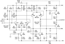
CIRCUIT DESIGN OF YES IT CAN DRIVE AN F4
The main goals of this board are (i) to use and to exploit tightly matched BJTs, thanks to the BJT Simple Matcher from BAF 2024; (ii) to provide high gain and wide output swing -- 20V (peak) -- without any shenanigans or funny business on the power supplies. Just use the same ±23V rails as the amp channel, and be able to swing > ±20V on the output.
Goal (i) is met by choosing Q5 and Q9 in the circuit, to be a pair of tightly matched BC546C devices. The schematic asks for matching within plus or minus 0.3 mV; but in the real world you'd just test 30 or 50 NPNs and then select the two pairs with best matching (one pair for the Left channel, one for the Right). If you can't quite get 0.3 millivolt matching, it's not the end of the earth. And if you can get better than 0.3 mV matching, how lovely for you.
Notice that there is only one capacitor in the signal path: input coupler C1, a high quality polypropylene film capacitor by Wurth. C1 blocks any DC offset that may be present on the input ("J6") from polluting the circuit and its output.
The circuit is designed to drive an F4, which includes a pair of AC coupling capacitors between the F4 input buffer and the (large) F4 push-pull output stage. Therefore I have omitted a coupling capacitor at the output of Yes It Can Drive An F4; one is already installed, on the F4 amp-channel PCB. If anyone plans to use Yes It Can Drive An F4 in a completely different application, without an F4 amp-channel, they ought to think very hard about whether or not to AC couple the YICDAF4 output.
CIRCUIT DESIGN: PART 2
Yes It Can Drive An F4 is a two stage amplifier; the first stage is (Q5+Q9) with (Q6+Q8) current mirror load. The second "voltage amplifying" stage is (Q10+Q11) with Q12 constant current load.
Because it's a two stage amplifier taking its output directly from the collector of the 2nd stage, the circuit is not able to drive a low impedance load. But that doesn't matter since the F4 amp channel board is a high impedance load. It's 100K ohms, which is easy to drive, even for this scrawny two stage amplifier.
Bias current for the two amplifying stages is provided by reference current generator Q3, which drives a first current mirror (Q4, Q7) for the first stage, and which also drives a second current mirror (Q4, Q12) for the second stage. The bias current flowing in Q3 is set by zener diode ZD1 and emitter resistor R6:
IcollectorQ3 = Iemitter = (Vzener - VBE) / R6
Plugging in numbers, Icollector of Q3 works out to be approx 2.7 milliamps. Oh by the way, after enduring the tenacious, obstinate, unrelenting "recommendation" of member @6L6, I eventually installed a pilot light LED "D1" in this 2.7mA current path. When power is applied and current is flowing, this LED lights up and reassures you that the circuit board is properly connected to the supplies.
The first stage's bias current is just a resistor ratio multiplication of the reference current
IcollectorQ7 = IcollectorQ4 * (R7 / R11)
In the same exact fashion, the second stage's bias current is another resistor ratio times Ireference
IcollectorQ12 = IcollectorQ4 * (R7 / R20)
It's illuminating to notice that the second stage transistors which drive the output (Q11, Q12), can EACH swing almost all the way to their respective supplies, VTOP and VBOT. Other designs for the second stage constant current source (Q12 here), cannot swing nearly as close to the CCS supply. The current mirror topology is the king of this particular hill.
I have specified the ultra fast and ultra low capacitance diode 1N4151 for position D2. Its part number is exactly 3 greater than the ubiquitous junkbox diode 1N4148, and indeed these two diodes are blood brothers. Diodes whose final eTest measurements are excellent, fall into the 1N4151 bin. And the rest of the diode batch, the average and the mediocre, fall into the 1N4148 bin. I think it's a Good Idea for serious DIYers to have a bag of ten or twenty 1N4151s in their parts cabinet, for those occasions when a super fast or super low capacitance diode, matters. But if you disagree, if you don't want to spend 20 cents on a new diode part number, by all means please feel free to use 1N4148s instead. The circuit's performance will suffer only a very small amount.
FOR EXPERT DESIGNERS: GAIN-BANDWIDTH, SLEW RATE, AND INDUCTOR L1
Yes It Can Drive An F4 uses an extremely well studied topology with (at first glance) completely standard Pole-Splitting "Miller" compensation. James Solomon's 1974 tutorial article (link) models it quite well; we can populate Solomon's equations by inspection, yielding the circuit's gain bandwidth product and slew rate:
GBWP = { 1/[(1/gmQ5)+R10] } / C5
SR = IcQ7 / C5
thus GBWP = 9.0E7 radians/sec = 14 MHz
and SR = 100 volts/microsecond.
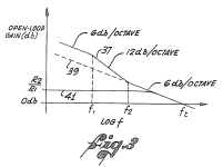
Now let's consider the effect of the inductor L1 in the "tail" region of the Long Tailed Pair, Q5-Q9. This turns out to be quite an old idea; according to Scott Wurcer here on the DIYA Forums, Richard Burwen of Analog Devices used it in 1966(!) on the hybrid discrete opamp "ADI121", shown in the attachments below. Later, Deane Jensen was able to take out a patent (US 4,287,479) on the same circuit. I've snipped out "Figure 3" of Jensen's patent and attached it below.
At very low frequencies, the inductor acts like a short circuit, so the emitter degeneration resistors R10,R13 are removed from the circuit at low frequencies. This has two benefits: (i) the noise contributed by R10 and R13 is eliminated at low frequencies; and (ii) the effective transconductance of the long tailed pair stage is greatly increased. In this circuit, gm rises from 2.4 millisiemens to 52 millisiemens -- a growth of 20X (26 dB). There is 26 dB more gain available at low frequencies, thanks to the inductor. That's 26 dB more negative feedback for distortion reduction. And, oh by the way, the Gain-Bandwidth Product increases by this same factor of 20X at low frequencies. It rises from 14 MHz to 280 MHz. Cowabunga.
I encourage expert readers to derive expressions for "f1" and "f2" (the pole frequency and the zero frequency introduced by inductor L1). I think you'll be pleasantly surprised at how high these break frequencies actually are. I think you'll be delighted at how much extra gain / distortion reduction is made available at 20 kilohertz. All for the cost of a single inductor.
DON'T DO ANY OF THE FOLLOWING, THEY ARE BAD IDEAS
First: I have set the gain of Yes It Can Drive An F4 to 20 volts per volt (+26 dB). An input of 1 volt (peak) produces an output of 20 volts (peak), which is the maximum input signal allowed by an F4. Don't attempt to change the gain unless you really know what you're doing. If you need someone to help you change the gain, that means: you don't really know what you're doing. Stop now.
Second: Don't reduce the gain below four volts per volt (4.0X = +12 dB). If you do, there is a very good chance the circuit will oscillate, blowing your tweeters and perhaps also destroying the power transistors on your F4. If you need gain less than 4X, switch to a different design without this limitation.
Third: Don't put this circuit into an amplifier that is wildly different from the standard, stock F4 as documented by Nelson Pass. In particular, don't run at supply rail voltages greater than 29 volts. Neither the transistors nor the capacitors will survive at higher voltage; you will need to design a new circuit with different components and possibly different topology.
Fourth: Don't drive a load impedance less than about 25 Kohms. If you NEED to drive a lower impedance load, you will need a different circuit. This one is designed for the F4 which presents a high impedance load.
Fifth: Don't experiment with other values of inductance. Either use 680 microhenries (choose an inductor whose self resonance frequency is the highest Mouser will sell you), or else omit the inductor entirely and don't stuff or solder anything into the L1 footprint on the board.
A couple of small tweaks later the newest release (rev B), which I hope is the final release, is presented here in this thread. You can see a top view of its unpopulated PCB, and also the circuit schematic diagram, in the attachments below.
WHAT IS F4 AND WHY DO I MENTION IT HERE?
F4 is one of Nelson Pass's many FirstWatt amplifiers (link). Unusually, the F4's circuitry is arranged as a Unity Gain Buffer: although F4 provides enormous current gain, its voltage gain is only 1X. To get the maximum available output, 20V (peak), you must supply an input of 20V (peak). A large number of DACs, streaming devices, smart phones, and linestages are unable to swing their outputs to 20V (peak), so these are not a good match for the FirstWatt F4.
In fact, it is so rare to encounter a line level device which CAN swing its outputs to 20V (peak), that a snarky catch phrase has arisen here on diyAudio:
- Yeah, yeah; but can it drive an F4?
The board is designed to be installed within an F4 chassis and to use the existing F4 DC rail voltages, with NO modifications of the F4 power supply or the F4 amp channel. Just bolt in the new boards, one per channel, and wire them up. Done.
DOUBLE DECKER / PIGGY BACK MOUNTING OPTION
This circuit board is 50mm X 90mm; its mounting holes are 40mm X 80mm. Which is a perfect match to the left hand (or right hand) set of four mounting holes on the F4 PCB: 40mm X 80mm. Using spacers, you can mount it directly atop an existing F4 PCB, in Piggy Back (Double Decker) fashion. Please see the attached photographs.
An F4 amplifier channel board (blue PCB) has a Yes It Can Drive An F4 (black PCB) mounted directly above. The spacers in this picture are 20mm tall (M3 female, hex body, M3 male) but Amazon also sells 25mm tall spacers if you prefer longer. The male ends of the spacers replace the M3 screws which secure the F4 amp channel to its heatsink.
Of course, builders are free to mount their Yes It Can Drive An F4 boards wherever they wish, in whatever orientation they like; there's certainly no requirement to use the piggy back mounting scheme.
YOU CAN ZIP-TIE Q5 AND Q9 FOR BEST THERMAL CONTACT
I've arranged the PCB footprints of the matched pair Q5-Q9, so you can zip tie them together (face to face) before stuffing and soldering. Personally, I solder all six legs and then cut off the zip tie, before I scrub the board with 99% isopropyl alcohol to remove flux and grunge. See the attached photo with a thin red arrowhead that points to the matched pair of transistors.
After I'm all finished with IPA and other solvents, then and only then do I apply a dab of heatsink thermal grease between Q5 and Q9. Finally I zip tie them back together again. This time: forever.
CIRCUIT DESIGN OF YES IT CAN DRIVE AN F4
The main goals of this board are (i) to use and to exploit tightly matched BJTs, thanks to the BJT Simple Matcher from BAF 2024; (ii) to provide high gain and wide output swing -- 20V (peak) -- without any shenanigans or funny business on the power supplies. Just use the same ±23V rails as the amp channel, and be able to swing > ±20V on the output.
Goal (i) is met by choosing Q5 and Q9 in the circuit, to be a pair of tightly matched BC546C devices. The schematic asks for matching within plus or minus 0.3 mV; but in the real world you'd just test 30 or 50 NPNs and then select the two pairs with best matching (one pair for the Left channel, one for the Right). If you can't quite get 0.3 millivolt matching, it's not the end of the earth. And if you can get better than 0.3 mV matching, how lovely for you.
Notice that there is only one capacitor in the signal path: input coupler C1, a high quality polypropylene film capacitor by Wurth. C1 blocks any DC offset that may be present on the input ("J6") from polluting the circuit and its output.
The circuit is designed to drive an F4, which includes a pair of AC coupling capacitors between the F4 input buffer and the (large) F4 push-pull output stage. Therefore I have omitted a coupling capacitor at the output of Yes It Can Drive An F4; one is already installed, on the F4 amp-channel PCB. If anyone plans to use Yes It Can Drive An F4 in a completely different application, without an F4 amp-channel, they ought to think very hard about whether or not to AC couple the YICDAF4 output.
CIRCUIT DESIGN: PART 2
Yes It Can Drive An F4 is a two stage amplifier; the first stage is (Q5+Q9) with (Q6+Q8) current mirror load. The second "voltage amplifying" stage is (Q10+Q11) with Q12 constant current load.
Because it's a two stage amplifier taking its output directly from the collector of the 2nd stage, the circuit is not able to drive a low impedance load. But that doesn't matter since the F4 amp channel board is a high impedance load. It's 100K ohms, which is easy to drive, even for this scrawny two stage amplifier.
Bias current for the two amplifying stages is provided by reference current generator Q3, which drives a first current mirror (Q4, Q7) for the first stage, and which also drives a second current mirror (Q4, Q12) for the second stage. The bias current flowing in Q3 is set by zener diode ZD1 and emitter resistor R6:
IcollectorQ3 = Iemitter = (Vzener - VBE) / R6
Plugging in numbers, Icollector of Q3 works out to be approx 2.7 milliamps. Oh by the way, after enduring the tenacious, obstinate, unrelenting "recommendation" of member @6L6, I eventually installed a pilot light LED "D1" in this 2.7mA current path. When power is applied and current is flowing, this LED lights up and reassures you that the circuit board is properly connected to the supplies.
The first stage's bias current is just a resistor ratio multiplication of the reference current
IcollectorQ7 = IcollectorQ4 * (R7 / R11)
In the same exact fashion, the second stage's bias current is another resistor ratio times Ireference
IcollectorQ12 = IcollectorQ4 * (R7 / R20)
It's illuminating to notice that the second stage transistors which drive the output (Q11, Q12), can EACH swing almost all the way to their respective supplies, VTOP and VBOT. Other designs for the second stage constant current source (Q12 here), cannot swing nearly as close to the CCS supply. The current mirror topology is the king of this particular hill.
I have specified the ultra fast and ultra low capacitance diode 1N4151 for position D2. Its part number is exactly 3 greater than the ubiquitous junkbox diode 1N4148, and indeed these two diodes are blood brothers. Diodes whose final eTest measurements are excellent, fall into the 1N4151 bin. And the rest of the diode batch, the average and the mediocre, fall into the 1N4148 bin. I think it's a Good Idea for serious DIYers to have a bag of ten or twenty 1N4151s in their parts cabinet, for those occasions when a super fast or super low capacitance diode, matters. But if you disagree, if you don't want to spend 20 cents on a new diode part number, by all means please feel free to use 1N4148s instead. The circuit's performance will suffer only a very small amount.
FOR EXPERT DESIGNERS: GAIN-BANDWIDTH, SLEW RATE, AND INDUCTOR L1
Yes It Can Drive An F4 uses an extremely well studied topology with (at first glance) completely standard Pole-Splitting "Miller" compensation. James Solomon's 1974 tutorial article (link) models it quite well; we can populate Solomon's equations by inspection, yielding the circuit's gain bandwidth product and slew rate:
GBWP = { 1/[(1/gmQ5)+R10] } / C5
SR = IcQ7 / C5
thus GBWP = 9.0E7 radians/sec = 14 MHz
and SR = 100 volts/microsecond.
Now let's consider the effect of the inductor L1 in the "tail" region of the Long Tailed Pair, Q5-Q9. This turns out to be quite an old idea; according to Scott Wurcer here on the DIYA Forums, Richard Burwen of Analog Devices used it in 1966(!) on the hybrid discrete opamp "ADI121", shown in the attachments below. Later, Deane Jensen was able to take out a patent (US 4,287,479) on the same circuit. I've snipped out "Figure 3" of Jensen's patent and attached it below.
At very low frequencies, the inductor acts like a short circuit, so the emitter degeneration resistors R10,R13 are removed from the circuit at low frequencies. This has two benefits: (i) the noise contributed by R10 and R13 is eliminated at low frequencies; and (ii) the effective transconductance of the long tailed pair stage is greatly increased. In this circuit, gm rises from 2.4 millisiemens to 52 millisiemens -- a growth of 20X (26 dB). There is 26 dB more gain available at low frequencies, thanks to the inductor. That's 26 dB more negative feedback for distortion reduction. And, oh by the way, the Gain-Bandwidth Product increases by this same factor of 20X at low frequencies. It rises from 14 MHz to 280 MHz. Cowabunga.
I encourage expert readers to derive expressions for "f1" and "f2" (the pole frequency and the zero frequency introduced by inductor L1). I think you'll be pleasantly surprised at how high these break frequencies actually are. I think you'll be delighted at how much extra gain / distortion reduction is made available at 20 kilohertz. All for the cost of a single inductor.
DON'T DO ANY OF THE FOLLOWING, THEY ARE BAD IDEAS
First: I have set the gain of Yes It Can Drive An F4 to 20 volts per volt (+26 dB). An input of 1 volt (peak) produces an output of 20 volts (peak), which is the maximum input signal allowed by an F4. Don't attempt to change the gain unless you really know what you're doing. If you need someone to help you change the gain, that means: you don't really know what you're doing. Stop now.
Second: Don't reduce the gain below four volts per volt (4.0X = +12 dB). If you do, there is a very good chance the circuit will oscillate, blowing your tweeters and perhaps also destroying the power transistors on your F4. If you need gain less than 4X, switch to a different design without this limitation.
Third: Don't put this circuit into an amplifier that is wildly different from the standard, stock F4 as documented by Nelson Pass. In particular, don't run at supply rail voltages greater than 29 volts. Neither the transistors nor the capacitors will survive at higher voltage; you will need to design a new circuit with different components and possibly different topology.
Fourth: Don't drive a load impedance less than about 25 Kohms. If you NEED to drive a lower impedance load, you will need a different circuit. This one is designed for the F4 which presents a high impedance load.
Fifth: Don't experiment with other values of inductance. Either use 680 microhenries (choose an inductor whose self resonance frequency is the highest Mouser will sell you), or else omit the inductor entirely and don't stuff or solder anything into the L1 footprint on the board.
Attachments
-
 PCB_top_view_revB.png211.8 KB · Views: 1,501
 -
Gerbers_Yes_itdrives_F4_revB.zip105.5 KB · Views: 201
-
PartsList_Yes_ItDrives_F4_revB.zip4.2 KB · Views: 203
-
Yes_It_Can_Drive_F4_schematic_revB.pdf33.2 KB · Views: 380
-
 Jensen_Fig3.png326.9 KB · Views: 1,027
 -
 thermally_coupled_BJTs.jpg451 KB · Views: 1,011
 -
 stacked_oblique.jpg297.3 KB · Views: 1,979
 -
 raster_scan_schematic_revB.png130.8 KB · Views: 1,667
 -
 stacked_daughter.jpg462.3 KB · Views: 1,509
 -
 ADI121_Richard_Burwen_1966_inductors.jpg94.2 KB · Views: 1,333
Last edited:

Simply fantastic! I'm ordering stuff to try this right now!
🙂
🙂
JLCPCB order is in! Thanks Mark for such a fun, practical, and well done design!
Last edited:
Pass DIY Addict
Joined 2000
Paid Member
Super awesome, Mark! Looks like my F4 will need to come back into the rotation again soon! With the cooler weather, I was just about to move back to my Aleph-J.

Single ended F4.
Solid state driving F4. Then you listen to a Conrad Johnson preamp, 20Vrms, with the F4 and you realize that there's driving the amp and there's making awesome music.
Tubes, man, tubes. The sound of tubes as voltage amp, driving a current amp.
The only thing that compares it, IMHO, is ZM's Iron Pre Bal driving a BA3 into the F4... better if bridged and balanced... until such time as they make a tube preamp that can swing the voltage in balanced mode..... Hint, ARC doesn't, I checked.
But, but, then Iron Pre Balanced kicked out the CJ ET3SE line stage from my rack. Driving the A5s. THANKS ZM. Hmmm...
The F4 is a chameleon.
Bridged F4.
I'm currently driving the Iron Pre Bal to a BA3 balanced to a pair if bridged F4s.
( I also drive the Iron Pre via the SE to the A5s)
I know, I sort of gave up on Macho SIT, it just couldn't drive 88db/watt speakers, it kept self immolating itself... but the bridged F4 are heroic.
This board is nice... but, but until you've heard the bridged F4s... you haven't heard what they can do.
Conclusion
Don't waste your time on an SE F4 unless your speakers are like 98db/w. Otherwise move up to the bridged set up.
Last edited:
Well I appreciate the effort you put in.
Thanks Mark Johnson.
sp
Thanks Mark Johnson.
sp
You keep wanting to put an FE into your amps, huh?
But if you do that, you sort of hobble the F4. You make it into a normal amp. Why not just put those boards into a different chassis, call it, say, the Dneu Balanced YICDAF4 and then you can play swapping front ends? The way your BA3 is put together.
Hint- we know each other's systems.
But if you do that, you sort of hobble the F4. You make it into a normal amp. Why not just put those boards into a different chassis, call it, say, the Dneu Balanced YICDAF4 and then you can play swapping front ends? The way your BA3 is put together.
Hint- we know each other's systems.
This is awesome. Thank you Mark!
98db ( when actually true ) is flea watt territory. Ive pushed speakers as low as 90db to irresponsible levels with a single F4. Granted, efficiency isn’t everything and there are other variables at play…but still, we don’t want to deny those with “less” efficient speakers the magic of the F4.
😁
98db ( when actually true ) is flea watt territory. Ive pushed speakers as low as 90db to irresponsible levels with a single F4. Granted, efficiency isn’t everything and there are other variables at play…but still, we don’t want to deny those with “less” efficient speakers the magic of the F4.
😁
Mind you, I'm not discouraging others from the magic of an F4, it is indeed a fine amp in that you are hearing the sound of the preamp. If your preamp can swing it, definitely go for it, if not, well, Mark's design and the BA3 will do the job finely. I'm just pointing out that it can be even better. Get more of Mark's boards then... build it into a balanced design.
Currently I got a pair of 90 db/w speakers hooked up to the bridged F4s. These same speakers were previously hooked up to a single F4. They played well enough, but for sure not at rock levels. They sounded a little bit congested.
In bridged mode, even at the same perceived loudness, there is a lot more bass. The quality of the sound is now effortless, the system has dynamics that it didn't have before.
Now, this could be the effect of changing the preamp too... but I have tried four different preamps ( two of them were 20Vrms CJ, as before ) with the single SE F4 and then the BA3B-F4 combo and I can attest this effect is due to going balanced and bridged.
I do suppose that if you found a good sounding, high output, balanced preamp, you could also achieve nirvana. I'm still playing around with them.. the end goal is to hook them up to the Maggies 1.7s. A cruel load indeed.
The F4 is indeed a fine amp.
Last edited:
Here's a Mouser cart for the "Yes It Will Drive An F4" BOM.
https://www.mouser.com/ProjectManager/ProjectDetail.aspx?AccessID=09824c19e2
One cart is enough parts for a pair of boards.
https://www.mouser.com/ProjectManager/ProjectDetail.aspx?AccessID=09824c19e2
One cart is enough parts for a pair of boards.
Yes, have the boards made up at your leisure with the gerber files Mark kindly shared in post #1
Here's a Mouser cart for the "Yes It Will Drive An F4" BOM.
https://www.mouser.com/ProjectManager/ProjectDetail.aspx?AccessID=09824c19e2
One cart is enough parts for a pair of boards.
This is fantastic! Thank you!!
One very important thing of note, you will want to order a much bigger number of BC546c, as these must be very tightly matched for the circuit to work. As it turns out, (100) of them is a significant price break, and costs only $5.40.
Very good point @6L6
I will update that part cound to 100 qty in the Mouser cart linked in post #14.
I will update that part cound to 100 qty in the Mouser cart linked in post #14.
This is fantastic! Thank you!!
One very important thing of note, you will want to order a much bigger number of BC546c, as these must be very tightly matched for the circuit to work. As it turns out, (100) of them is a significant price break, and costs only $5.40.
Will you do a build plan for this? And how to match them?
- Home
- Amplifiers
- Pass Labs
- Yes It Can Drive An F4 -- an example circuit using tightly matched bipolar transistors