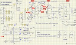
Look at the schematic.
We have a 3rd Cap not directly involved in the signalpath (C5) also 0,22uF.
Should this also be lower value? What is it for?
Thx
We have a 3rd Cap not directly involved in the signalpath (C5) also 0,22uF.
Should this also be lower value? What is it for?
Thx
That calculator is misleading. The relevant resistance is not the load, but load plus source. In many cases this does not matter very much as the load is much bigger than the source, but in valve circuits it often does matter.Max Martin said:Maybe this is some help?
C5 is very much involved in the signal path. It provides the AC ground for the other input to the LTP phase splitter. Together with the 1M resistor it forms a high pass filter, so it has a similar effect to a coupling capacitor. As general guidance, you should ensure that the LF rolloff defined here is quite different from that defined by other coupling caps so you don't get excessive phase shift all together - the designer has done this, so don't mess up his design in this respect.We have a 3rd Cap not directly involved in the signalpath (C5) also 0,22uF.
Should this also be lower value? What is it for?
Another piece of general guidance: to successfully modify a circuit you need to understand it better than the original designer.
So you're saying that i should keep all caps at 0,22UF (totally six for both channels) ?
There is now advantage using 0,1uF in all postions if i want a an early roll-off as i use this amp to power mid/tw sections?
Is it wise to lower the cathode-bypass cap to "loose" bass instead?
In my preamp as you maybe saw in the other thread i should have an roll-off around 6-9Hz. (1uF/1M)
There is now advantage using 0,1uF in all postions if i want a an early roll-off as i use this amp to power mid/tw sections?
Is it wise to lower the cathode-bypass cap to "loose" bass instead?
In my preamp as you maybe saw in the other thread i should have an roll-off around 6-9Hz. (1uF/1M)
To get an earlier rolloff I would reduce C6 and C7. This is quite late in the circuit. Better, add the coupling caps the designer should have put around the volume control, especially between the slider and the first valve grid.
Changing cathode bypass caps moves a shelf, not a rolloff. Over a limited frequency range it can change phase more than amplitude so it can be a useful way of tuning for LF loop stability. You need to know about Bode plots, or how to carefully interpret the results of a simulation.
1uF/1M will give rolloff at about 0.15Hz, not 6-9Hz.
Sorry, i can't understand what you mean with "slider"? Volume?
I have removed the volumepot. Signal goes straight into the 12ax7. I use this as a poweramp only. You mean a coupling cap here? What value you can recommend?
Whatabout a grid-stopper. Recommended with 12ax7?
I have removed the volumepot. Signal goes straight into the 12ax7. I use this as a poweramp only. You mean a coupling cap here? What value you can recommend?
Whatabout a grid-stopper. Recommended with 12ax7?
Silly me! I foolishly assumed that the circuit you have put up is the circuit you have, so I didn't bother to re-read the entire thread to check for changes you have made.
At the input to a circuit there should almost always be a coupling capacitor, to isolate the circuit from whatever comes before. This is also usually the best place to set the LF rolloff, as signal levels are low so capacitor distortion will not be a problem and unwanted signals don't get a chance to intermodulate through the circuit.
At the input to a circuit there should almost always be a coupling capacitor, to isolate the circuit from whatever comes before. This is also usually the best place to set the LF rolloff, as signal levels are low so capacitor distortion will not be a problem and unwanted signals don't get a chance to intermodulate through the circuit.
It was maybe a bit silly of me to load up a schematic that is orginal. Sorry I don't have skills to do one new with the mods. Only difference is caps are 0,47uF and volumepot removed (including the small 150R to ground with that)
Ok, I understand. But how big or small cap would you place here?
And one other thing, the negative feedback. Is it only implented when use with 8ohm speakers? Seems like that when i check the schematic... I have 4 0hm speakers all the time so i can just remove that feedback OR? (pcb is packed with stuff as it is)
Yes, the slider means the volume control. You have a 39k grid load resistor at the input of the 12AX7, so you can connect a good quality 0.027uF capacitor between the input jack to the grid to create a 150Hz high pass filter. Leave the other coupling capacitors as they are.
It's 510K. Schematic is wrong. What does it change regarding cap size?
EDIT: SO that means i was wrong too about input imp 🙁 Sorry. It is 510K.
EDIT: SO that means i was wrong too about input imp 🙁 Sorry. It is 510K.
Last edited:
For 510K, then try 2nF (0.002uF), the formula is C=1/6.28*R*F, R is the resistance, and F is the corner frequency.
You can't expect us to keep track ourselves of all the changes you have made. Better for you to learn how to calculate coupling cap values. It isn't difficult.
The feedback is in operation whichever output tap you use. For 8R it comes directly from the output. For 4R it uses the OPT secondary as an audio autotransformer.
The feedback is in operation whichever output tap you use. For 8R it comes directly from the output. For 4R it uses the OPT secondary as an audio autotransformer.
You can't expect us to keep track ourselves of all the changes you have made.
I didn't say that.
Even though mathematics is very hard for me I will try then. Not so hard for you can be very tough for another.
I will try with that small cap.
Appreciate your help.
Thx Jazbo8 and DF96
The feedback is in operation whichever output tap you use. For 8R it comes directly from the output. For 4R it uses the OPT secondary as an audio autotransformer.
It works like that. Thanks. Always wondered.
It works like that. Thanks. Always wondered.
Ideally you should connect feedback to whatever tap used for speakers and feedback circuit should be adjusted accordingly. But this is hard to implement, unless switching is automated using microprocessor, to prevent any circuit changes while amp is running.
Ideally you should connect feedback to whatever tap used for speakers and feedback circuit should be adjusted accordingly. But this is hard to implement, unless switching is automated using microprocessor, to prevent any circuit changes while amp is running.
So if I understand correct, yaqin have taken a shortcut and only placed feedback over 8R just because most people have 8 ohm speakers or?
If i look inside my Yaqin there is only one red wire going from feedback (12K and 50pF) direct to speakconnector 8 ohm, nothing to 4ohm?
Edit: ok for best performance it should be feedback wire connected to 4R if i use 4 ohm speakers?
Last edited:
Yes, yaqin have taken a shortcut - but a reasonable shortcut. If the OPT is good quality then there is little harm done.
To transfer the feedback connection to the 4R output would need a change in feedback components: resistor smaller, capacitor bigger (8k2 and 68pF, perhaps?).
To transfer the feedback connection to the 4R output would need a change in feedback components: resistor smaller, capacitor bigger (8k2 and 68pF, perhaps?).
thx DF96, i will try those values you mentioned and move over the wire to 4R speakerterminal. I will post back when i've tried it. I just ordered these values since i don't have them in stock.
Today my Yaqin developed a hum/buzz in right channel. It came right after I switch it off and on after same 2 hours use to change tubes in my preamp.
Hum/buzz get's better when it gets warm. And it's pretty low in freq. Is it that some elcos start to run bad (the one's one top are not bulging) But there is 6x 22uF/450V on the pcb.
I have the exact same noise in left channel too but much lower in volume (and i think it been there all the time)
Can it be that my KT88 start to run out of steam??
I checked bias and the last tube to the right (V4) is not giving me reading, all others are about 0,55V. And it's not as hot. I can touch it with my fingers. With the others i burn them if i do the same! I will try to swap V3 with V4 and see.
Last edited:
After swapping V4 with V3 i got same resultat except that now bias is not working on V3 now instead. Seems like the tube have died? First tube failure for me. Is this normal that tubes do this when they die? I was worried something happened to my amp.
- Status
- Not open for further replies.
- Home
- Amplifiers
- Tubes / Valves
- Yaqin MC-100B - not as powerful as advertised, but still a good value.