Hi Glenn,
It might be easier to see if the Vt line is stuck high, low or it varies. The voltage goes up for higher frequencies. The AM is normally only active when AM is selected, the same for FM only when FM is selected. Remember that on the FM band, you're looking at up to about 119 MHz with a scope rated at 100 MHz, -3dB down. So everything will start to look like a saw tooth or sine wave. That's true even if the actual wave form was a square wave because the higher harmonics in a square (or triangle) wave are well beyond what this scope can display. Second harmonic is about 240 MHz, a bit less. Any guesses for the third and forth harmonic? Even my Tek 2465B (400 MHz) will display a "soft" square wave if the real signal is a nice, sharp square wave. So your actual signal amplitude at a local oscillator frequency of 100 MHz (tuning 89.3 MHz) will be about 70% of what it really is. That's assuming the circuit can drive the probe / scope input capacitance. When you are working at the limits of your equipment, you should take these things into account. So don't worry when you aren't seeing exactly what you expect to see.
Getting back to the Vt line. It often gets stuck high if you aren't getting a local oscillator signal from the front end. You can actually cheat here by disconnecting the Vt signal and use a variable power supply to tune the front end. If you can tune stations with your power supply, the FM front end is mostly good, and if you are missing a signal, it is probably the buffer transistor, or a leaky / shorted ceramic disc capacitor at the LM7000 chip. Easy way to check this is to remove the capacitor and check if you now have a signal at the tuner side of the pads. The only thing that the Vt line stuck high or low means is that the feedback loop is open.
If you can't tune any stations with your power supply, it is likely that the oscillator transistor has failed, or another component in that circuit. Suspect solder joints and capacitors.
If the Vt line does vary with the tuned signal, that means the loop is closed and the oscillator and buffer are working and your fault could be in the mixer transistor, or the IF transformer. If you have an output at approximately 10.7 MHz (IF out pin from the tuner pack), you probably have a fault in the IF strip. Before we get into that, just confirm these basic signals so we know what we are dealing with.
-Chris
Thanks both. I don't have a variable power supply so will have to get one. Would a range of 0-15 V be suitable? In the meantime I will check our that AM signal on pin12. Glenn
Hi Glenn,
Yes, 0 ~ 15 VDC will allow you to check this. Some tuners need 23 V to reach 108 MHz, some only 12 V.
See if you can find an HP 6236A/B/C or a 6237A/B/C. These are excellent supplies with +/- 20 VDC (25 VDC not loaded heavily) and either a 6 VDC or 18 VDC variable supply. They are quiet (low noise) and reliable. I've got one since the 1970's, and have for a number of years more of them. The +/- supplies are very good for analogue testing. The 6V one does 5 VDC (TTL) very well. The 18 VDC supply would cover TTL and CMOS supplies. So one power supply covers your analogue and also digital sections of a project. You can bring up an entire solid state preamplifier with one of these supplies to at least partial & functioning operation if not having the rails completely up.
Hunt on Ebay for one of these Glenn. Shipping will be very little compared to getting it into Canada. Choose one that is clean looking, both meters need to be there and not broken or hanging free. HP made other power supplies that would do, but these are by far and away the most useful. If you can afford a new one, more power to you. They would be cleaner than these older ones, but these older ones are cleaner than most budget new supplies. You will probably have to clean the meter switch, but that isn't difficult.
I just looked. They range from $117 CDN to $175 CDN in clean, tested condition. That's like $90 USD to $135 USD (or best offer). That's pretty cheap for what you're getting.
-Chris
I did actually mention way back in March to try a variable voltage on Vt:
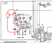
To do it more thoroughly, all you need do is remove these two parts and then add a preset or pot across the 30 volt tuning rail like this.
Another test that can be done is to isolate the tuning line (VT) and connect it instead to the wiper of a pot or preset pot (say 10k or 22k) and connect the pot across the 30 volt line. That would give you a manual tuning voltage from 0 to 30 volts and should allow stations to be tuned.
To do it more thoroughly, all you need do is remove these two parts and then add a preset or pot across the 30 volt tuning rail like this.
Attachments
OK, thanks to you both. I was looking at your earlier post Mooly but what you have just posted today makes things clearer for me. I'll try that but will have to buy a pot from the local electronics store. Chris, freight from US to Australia is horrendous- for something like the power supply it would be in the order of $150US. Also, we are on 240V so the unit would have comply with that requirement. Not always the case in my experience. However, I will continue to look around. As a short-term solution, I can buy a switching type variable supply locally from Radioshack type store for about $120 AUS. Range 0-24V. Or should I steer clear of that one? Glenn
A fixed resistor such as 22k would give you a valid tuning voltage of around 9 volts DC. Just pull Q2 from the circuit and tag the resistor from the collector pad to the 30 volt line.
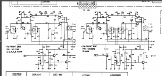
You would then need to scope the OSC line and delve into the tuner can itself. F out is the oscillator output. There are two versions of tuner depending on your region but the oscillator signal is the same for both.
If you go in the can do not physically move any parts or wires as that will alter the alignment. It has been aligned with the parts in that position and to move them would alter the parasitic coupling between them and change the alignment.
The scope with DC coupling can be used to probe around TR3 and see if there is any kind of high frequency signal present. You can also use the scope to check the DC voltages on TR3 and TR4 and see if anything looks amiss. The scope is probably better than a DVM for this when used with its 'times 10' 😉 probe.
Component values aren't marked because these RF units are considered non repairable but we never say never.
Attachments
Mooly, that schematic looks like the 550. In the 540, the AM antenna also goes into the can so some of the components may be different. I have not seen the schematic for the 540 and could not find one online. Glenn
That makes things much more difficult then. Without a circuit you have to 'busk it' as we used to say. There are still things you can do but it all gets more heavy. You would need to trace the OSC line in the can and identify where the oscillator is and then have a careful measure around the transistors to see if anything obvious showed up.
True RF work and faultfinding at component level isn't easy though 🙁
True RF work and faultfinding at component level isn't easy though 🙁
I'll post a photo so you can see what it looks like. Some of the components are hidden under the metal casing. Can't get at them without removing it. Glenn

There are two electrolytic capacitors in the charge pump low pass filter circuit which may cause the PLL tune voltage to sit at a minimum or maximum voltage if they go leaky or have higher than normal esr. Given the age of the tuner it may be easier to check these first before testing for RF faults.
The loopy nature of these synthesisers can be tricky to fault find.
The loopy nature of these synthesisers can be tricky to fault find.
Last edited:
Hi Indiglo, I did test these in-circuit and they seemed OK. Maybe I should pull them and check properly. Glenn
I'll post a photo so you can see what it looks like. Some of the components are hidden under the metal casing. Can't get at them without removing it. Glenn
That all looks pretty typical tbh...
There should be some RF from the OSC going to Pin 14 of the LM7000 even if the VCO is out of lock.
Have you checked to see if you have 12volts at the front end. You can check for 12volts at Inductor L1 at the front end. I'm working from a TX550 manual, it looks like 12volts comes from Q29 and it powers most of the receiver RF circuitry.
Have you checked to see if you have 12volts at the front end. You can check for 12volts at Inductor L1 at the front end. I'm working from a TX550 manual, it looks like 12volts comes from Q29 and it powers most of the receiver RF circuitry.
Last edited:
Hi Indiglo,
Please read back earlier. You are covering ground that has already been explored / explained. At the moment you can only confuse Glenn by going back in time.
Hi Glenn,
As Mooly said, that is a pretty standard tuner pack made by Alps. Just concentrate on seeing what signals are on the various pins. Follow Mooly's suggestion for varying Vt. I always use a power supply and clearly what Mooly has suggested can work for you right now. The value of the pot isn't that critical.
I forgot you are in Aus. In your user information, if you indicate what country you are from it will put a flag under your name. It would be very handy as a reminder.
Keep an eye out for one of these HP supplies. They are excellent value for what they are. and something you will use until you're my age and beyond.
-Chris
Hi PRR,
You bet! Solder joints, or the connections inside the capacitor are compromised. I would recommend replacing that capacitor simply because of the pull on the leads, even if it seems to work.
You have a good eye! I only saw this after looking at your sniped section of the photo. I would have had to download the picture and zoom into it in order to notice that, but the cap is on a funny angle before your eye is drawn to the snapped glue.
-Chris
Hi PRR, Chris, I did pull that cap and it tested OK for both capacitance and ESR. All the voltage test points on board also check OK so I assumed the power supply section was good. However, if you think the cap should go I shall replace it- if i manage to resolve the other issues. I thought the glue was a leak but have seen similar glue on other TX540 images. Glenn
Hi Glenn,
When the leads are pulled hard enough, they can have connection problems inside where they actually connect. Also, the rubber seal around the pins at the bottom may have defects now.
Where the pins still soldered to their pads?
Yes, once you have it working, then change the capacitor.
When the leads are pulled hard enough, they can have connection problems inside where they actually connect. Also, the rubber seal around the pins at the bottom may have defects now.
Where the pins still soldered to their pads?
Yes, once you have it working, then change the capacitor.
Chris, the cap was firmly soldered in place before I desoldered it. When I said pull I did not literally mean that I yanked it out. I was pretty gentle in removing it. My fault that it now sits at an angle but it is soldered back in place. I will post more after I test Vt with the variable voltage. Not sure if this unit will ever be working again but it has been an instructive project. Glenn
- Status
- Not open for further replies.
- Home
- Source & Line
- Analogue Source
- Yamaha TX540 tuner not tuning