🙂As a side note also please note that I liked 2 posts by @Lism audio not only for their content, but also because I thought he deserved a "thanks". ☕
What I said. I think it isn't very likely that a RFI capacitor that is shorted under normal operation may be the reason, and their soldering points aren't easily accessible.
Best regards!
Best regards!
hi,kay.
I fixed a AS3000 some years ago.the AS3000 didn’t work like yours.one channel didn’t work before I received it,then two channel didn’t work.
After checking and finding ,I replaced the two 100k SMD resistors by axial resistors,R94 & R287,the channel restored.the other channel restored after the same fixing.
I think that the root is the less-margin power rating of the resistors.


sorry my bad english.
X.G.
I fixed a AS3000 some years ago.the AS3000 didn’t work like yours.one channel didn’t work before I received it,then two channel didn’t work.
After checking and finding ,I replaced the two 100k SMD resistors by axial resistors,R94 & R287,the channel restored.the other channel restored after the same fixing.
I think that the root is the less-margin power rating of the resistors.
sorry my bad english.
X.G.
Interesting, thank you! How did you find it out? These resistors are on the Main 1 and Main 2 (the power amplifier) boards, aren't they? Well, these woulb be relatively easy to access.
Best regards!
Best regards!
Yes ,these resistors are on the Main 1 and Main 2 (the power amplifier) boards.
Initialy I didn’t check these resistors .
I checked that the forward voltage of D203 is zero(would be -2.?V if using DMM because of interfering),thus I knew the Q232 of CCS didn’t work.
Initialy I didn’t check these resistors .
I checked that the forward voltage of D203 is zero(would be -2.?V if using DMM because of interfering),thus I knew the Q232 of CCS didn’t work.
Last edited:
Admittedly I didn't do any measurements at the power amplifier boards, besides finding out that there's no or next to zero voltage at the speaker terminals, which I'd regard ok, despite those 48.5 V named in the SM 😱 .
As said in my first entries, the Self Diagnosis flash pattern isn't exactly covered in the SM. It was showing flash flash flash break, flash flash break, flash flash break etc. I was free to omit the first three flashes and concentrated on flash flash break, the Flashing 2 pattern, which points to PS Protection and a PRV voltage issue. Because my measurements regarding PRV offered no obvious findings besides the wrong PRV voltage itself all over this bus, I'm feeling lost here.
If the first three flashes also contain some information, this would be Flashing 4 pattern, pointing to PS Amp Protection 2. This also is nothing else than wrong PSU voltages, this time including the 22 mF filter capacitors, which I couldn't confirm.
If there were something wrong with the power amps, the flashing pattern presumably would point to either DC Protection (flash flash flash flash break etc.) or I Protection (flash flash flash flash flash etc.).
Best regards!
I would definitely try to connect the amp at another location. Friends, or neighbors or whatever other circuit.
Hugo
Hugo
Of course I could. But would it help me to find out that it refuses to work exclusively inside our home?
Best regards!
Best regards!

Some of the resistors you note as less rating are fusible for safety reasons. Fingers crossed that they are intact in this instance and have not gone high in value.hi,kay.
I fixed a AS3000 some years ago.the AS3000 didn’t work like yours.one channel didn’t work before I received it,then two channel didn’t work.
After checking and finding ,I replaced the two 100k SMD resistors by axial resistors,R94 & R287,the channel restored.the other channel restored after the same fixing.
I think that the root is the less-margin power rating of the resistors.View attachment 1211610View attachment 1211611View attachment 1211612
sorry my bad english.
X.G.
hi,mjona.
I don’t think that these resistors are fusible.IMO,the less rating of them is the root of the durable of AS3000 being not so good.
All PS of my AS3000 were okay before I repaired it,thus I can check the D203’ s volt after turning on .It didn’t work just because the speaker protect relays were inactive .
The most components of power amp are unreachable except for D203 etc .I found that the D203’s volt is indicating of VAS work,after I analyzed the power amp section by drawing the attached simplicity diagram.
The time of my fixing is short,and of my analysis is long because of the most components being unreachable.
Attachments

Last edited:
Page 2 in the SM says:Some of the resistors you note as less rating are fusible for safety reasons. Fingers crossed that they are intact in this instance and have not gone high in value.
Critical Components Information
Components having special characteristics are marked and
must be replaced with parts having specifications equal to those
originally installed.
The quotation misses the symbol that can be described as a triangle around an exclamation point. Resistors R93, R187, R94, R287 that X.G. has successfully replaced also are missing this symbol, hence aren't critical in Yamaha's sense. Instead, there's a black triangle next to them (and many other components), which Yamaha failed to explain.
Best regards!
Are you sure about that? What about this:Instead, there's a black triangle next to them (and many other components), which Yamaha failed to explain.

Thus, black triangle ---> Metal film resistor.
I am not impressed by the standard of Yamahas solder joints in the images posted by XG. One does not know how many of these compromise joint integrity.Page 2 in the SM says:
Critical Components Information
Components having special characteristics are marked and
must be replaced with parts having specifications equal to those
originally installed.
The quotation misses the symbol that can be described as a triangle around an exclamation point. Resistors R93, R187, R94, R287 that X.G. has successfully replaced also are missing this symbol, hence aren't critical in Yamaha's sense. Instead, there's a black triangle next to them (and many other components), which Yamaha failed to explain.
Best regards!
I'm confused by the mention of speaker protect relays. I would have thought that there would have been a signal from your dc protect circuit to the microprocessor to put the amplifier into power supply protect mode by opening RY1, a double pole type powering the sub transformer under all circumstances when the power switch is on and subsequently the main toroid when Q2 causes the relay to close.hi,mjona.
I don’t think that these resistors are fusible.IMO,the less rating of them is the root of the durable of AS3000 being not so good.
All PS of my AS3000 were okay before I repaired it,thus I can check the D203’ s volt after turning on .It didn’t work just because the speaker protect relays were inactive .
The most components of power amp are unreachable except for D203 etc .I found that the D203’s volt is indicating of VAS work,after I analyzed the power amp section by drawing the attached simplicity diagram.
The time of my fixing is short,and of my analysis is long because of the most components being unreachable.
Q2 base connection is hard to trace which microprocessor pin may be. At a guess possibly pin 48 with R574 a 100R resistor in the line. One could measure Q2 base voltage and that at pin 48 if so.
Kay did think this was a power supply protection fault which could include the sub transformer domain.
In this the dc conversion process involves a full wave bridge (D765-D768) after the secondary winding, charging C3 a 3300uF 16V capacitor. All components in this circuit block, active and passive, should be checked out for correct values and connection to the pcb.
I have seen blobs of solder in the images of the pcb's in your post. One would remake any joints that look dodgy and in particular look to see if there is a strong mechanical connection for the relay - i.e. legs twisted to keep the body securely in place on the pcb before solder has been applied.
Hi,mjona.Sorry for my mistake in last post about the speaker protect relays.
The AS3000 actually isn’t mine,is the 3th person’s.My friend had repaired it for several months before I received it.
I just read the records of my notebook,and the records show that the conditions of the AS3000 when I received it:
1.My friend had checked that all circuits were okay except for power amp ,and not found the fault.he detected that the music signals reached the input of power amp by scope monitoring.
2.The speaker protect relays were active after turning on .
3.the headphone sockets can output music signals,the speaker terminals cannot.
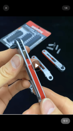
PS : Disassembling the power amp module out of the AS3000 enclosure maybe need a special screw driver in the attached pic.
The AS3000 actually isn’t mine,is the 3th person’s.My friend had repaired it for several months before I received it.
I just read the records of my notebook,and the records show that the conditions of the AS3000 when I received it:
1.My friend had checked that all circuits were okay except for power amp ,and not found the fault.he detected that the music signals reached the input of power amp by scope monitoring.
2.The speaker protect relays were active after turning on .
3.the headphone sockets can output music signals,the speaker terminals cannot.
PS : Disassembling the power amp module out of the AS3000 enclosure maybe need a special screw driver in the attached pic.
Attachments
Last friday I got my unit back again from the service station, where the protection device was fixed by replacing twelve Nichicon 47µ/35V electrolytics. Also the power switch was replaced., much to my surprise.
As said above, I yet had the suspicion that the protection circuitry itself may have been the culprit, but never would I have the idea to suspect and replace all these 'lytics. Maybe there's a Yamaha service bulletin for authorized repair shops with an according advice.
At home again, I measured all 12 capacitors. All capacitance values were 10 % low, but within the tolerances. ESR was about 1.3 to 1.5 Ω for all, which doesn't appear too bad. The power switch was bad indeed, as the contact points don't close. Which surprises me, as there at least was a reaction after throwing the switch.
All in all, I'm somewhat clueless, but also feel assured that never in my life I would have found the cause.
Best regards!
Looks to me as though the replacement of elcos is a standard routine, no matter what the fault is. How much did they charge?
- Home
- Amplifiers
- Solid State
- Yamaha A-S3000 ceased from working