That's a smart way of finding a short. So far i've gotten all of the PS drivers removed from the amplifier and the pad for R31 is still reading 0Ω to ground. Where else should I check. I'll keep following the trace and checking components
You should follow all traces that lead from the resistor pad that's connected to the driver board pad and from that driver board pad, as well. You need to follow on both sides of the board.
I'm not sure but R31 is reading 0Ω on 1 pad and 500 on the other, while R30 is reading 0Ω on one and 1 on the other which indicates a short correct?
Those resistors have one terminal connected to ground. The other terminal should not also read 0 ohms to ground.
How many components are currently out of the circuit (1 terminal desoldered for 2 terminal components qualifies it as out of the circuit)?
How many components are currently out of the circuit (1 terminal desoldered for 2 terminal components qualifies it as out of the circuit)?
i removed R30/R31 for ease of access to the pads without touching something else with my probe. All PS fets are out also and PS driver board
i'm sorry, it's reading open as if my probes aren't toughing at all on one end and 0Ω on the other pad of R30. It could be because that pad that is reading open is also connected to a pad where the driver board goes
I don't understand. Do this... resistance across the pads for both pairs of resistor pads and diode-check across both pairs of resistor pads in both directions (probe positions reversed). One resistance value for each pair of resistor pads. Two diode-check values for each pair of resistor pads. Post the EXACT value displayed on the meter, even if they are all zeros.


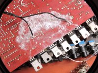
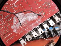
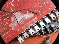
i was testing from the amp ground when i got the 0Ω, not between pads. So is what you see in the pics normal?
You may have inadvertently removed the fault but the PS FETs are very well isolated from that resistor. Removing them could not have removed a short circuit across that resistor.
I'm getting a new roof this weekend and i'll start putting the new PS Fets on the board but i'll test for faults after each Fet
Before installing any FETs, you need to check each FET location with a loading capacitor to confirm that all are producing an acceptable drive signal.
I'm sorry, i meant to say PS drivers is what I intend to start putting back on the board. I'll put R30/31 resistors back in also along with the driver board
do PS drivers have to be from the same batch? I have 10 from the same and 2 from another but all are new
Only components that are in parallel need to match. Output transistors that have very low value emitter/source resistors would be included in that designation. The drivers are not in parallel. They are driven by the same signals but drive independent circuits.
- Home
- General Interest
- Car Audio
- XXV Sampson power up issues