I can't tell anything from that photo. Is the bridging from traces or simply from solder bridges?
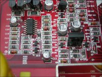
First leg of the PS drivers?
First leg of the PS drivers?
I hope this helps. The Zener and Resistor are crossed over one another and connected to the emitter of the KTA1275 and KTC3228. I get the best pics I can, it's very hard to hold my phone still but I have nerve damage from an incident during a year long trip to Afghanistan that involved a large boom and a mortor round. Any advice on ways to take better still and focused pics?

Those should connect to the base, not the emitter. See attached.
I know that people won't use a regular camera but you can buy a suitable old coolpix for ~$25. The atached is an example of what an old 2200 can do. It has a flash so you don't need to be able to hold it steady.
I know that people won't use a regular camera but you can buy a suitable old coolpix for ~$25. The atached is an example of what an old 2200 can do. It has a flash so you don't need to be able to hold it steady.
Attachments
they are connected to the base, i read the datasheet wrong. I'm going to get a stand for my digital microscope and see how that works. So what should I do? I have new PS Fets and output Fets ready when the amp is ready
You need to find what's shorting that resistor to ground. One end is supposed to be connected to ground but the other is not. Disconnect everything from that trace to see if any eliminate that 0 ohm connection.
I don't need any more photos at this point.
I don't need any more photos at this point.
which of the legs on the PS drivers connect to ground? Is it the "base" leg? Just asking to make sure, i want to check all of those for shorts to that trace the resistor is on
gonna change the subject for a sec...how much wiggle is acceptable with these caps? I can move them 8-10mm either way with no force. All of the others are solid

It could indicate a couple of things.
The were not seated all of the way down when installed.
They have been forced to the side and the leads have been pulled partially out of the capacitor.
The first isn't an issue. The second could be a problem. I'd desolder one solid one and one Weeble and examine the terminals. You can generally tell when the terminals have been partially pulled out.
I checked ohm readings of all 3 NPN/PNP PS drivers banks and they read the same as each other within a few Ω of one another. I feel I need to take the PS drivers back out, test the pads and vias for ohms, if no short is apparent I'll install them one by one and check for a short after each one. There is continuity between B+ and Neg on the amp and I noticed the dip pins for protect that is on the board next to where the driver board is mounted
Continuity!?!?!?
It's meaningless. unless your testing a fuse or an incandescent lamp/bulb.
When you post something like that, post the exact reading on the display and post the points where you had each meter probe.
It's meaningless. unless your testing a fuse or an incandescent lamp/bulb.
When you post something like that, post the exact reading on the display and post the points where you had each meter probe.
I am learning as I go, I can't read schematics, never had any training so I'm not always sure of the term I should use or what i'm testing for. I don't like asking how to do everything because I want to learn some things myself. I know what schematic symbols are because I've learned it in the "solid state devices" class i'm taking.
Whether I have the DMM set to diode test or 2000Ω, the reading keeps climbing. I'm still removing the PS drivers so soon I hope to find where the fault was
Whether I have the DMM set to diode test or 2000Ω, the reading keeps climbing. I'm still removing the PS drivers so soon I hope to find where the fault was
Don't try to reinvent the wheel. Get as much information as possible from others. When I was starting out, I only wanted to get the bare minimum and learn the rest on my own. I was an idiot (still amp to some degree).
Ask questions. I've been doing tech support for 20+ years. Answering a few more questions is not a problem.
At this point, do you still read 0 ohms across the pads for R31?
Ask questions. I've been doing tech support for 20+ years. Answering a few more questions is not a problem.
At this point, do you still read 0 ohms across the pads for R31?
no i don't have any of that. I did forget one rule when i replaced the PS drivers, I didn't replace all of them so that they would all be from the same batch. While I was getting the short to ground at R31, there were PS drivers with 2 different batch numbers installed I noticed while removing them all. I have enough new ones to install that are all of the same batch. I'm sure that wouldn't cause a short to ground condition though right?
The 'matching rule' applies to components operating in parallel. The drivers are not in parallel. It certainly won't hurt to have all matching driver.
If you can't find the problem soon, pick up come canned air (computer keyboard duster). You can use it (can inverted) to freeze the board and possibly find a short by applying voltage (through a resistor or other limiter) to the point that's shorted to ground but shouldn't be.
If you can't find the problem soon, pick up come canned air (computer keyboard duster). You can use it (can inverted) to freeze the board and possibly find a short by applying voltage (through a resistor or other limiter) to the point that's shorted to ground but shouldn't be.
i still don't understand how i'll be able to find a short by freezing the board with an inverted can of air duster. What is the magic that happens to find a short? I'll search for more info and possibly a video on what is done
When excessive current flows through traces, they heat up. If you freeze the board (will be coated with a layer of ice crystals) and apply current to the shorted terminal of the driver board/resistor, the trace may heat up (no guarantees) and point you to the direction of the short to ground. I'd suggest using a 2 ohm (dummy load type) resistor. When a trace heats up (only needs to heat up a few degrees), you will see a distinct line in the crystals. Again, there are no guarantees that this will be of any use.
You would apply the limited voltage for a few seconds at a time, increasing the time applied up to about 10 seconds. If that doesn't show the heating, it likely never will. You'd freeze both sides of the board.
This can be used for other things as well, such as finding a defective op-amp in a group of directly connected op-amps. Instead of removing/replacing multiple IC, the defective op-amp will often defrost more quickly than others and you have your defective IC. I've had to do this many times for the old MTX amps that very commonly had defective op-amps (possibly because they operated them on ±18v).
- Home
- General Interest
- Car Audio
- XXV Sampson power up issues