Designing for dual woofers?
Dear Mr Waslo and all,
I have a very nice pair of Klipsch KG 5.5's that I want to improve. These are a TWW system; horn loaded dome tweeter with a pair of 10"woofers in a two way arrangement.
I understand that dual woofers in a two way means lobing in the vertical axis.
My question then is; is it possible to improve the system keeping the 2 way configuration through the crossover?
Some data attached to show my approach:
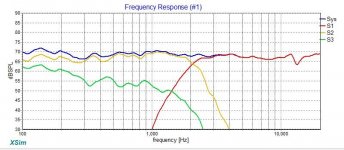
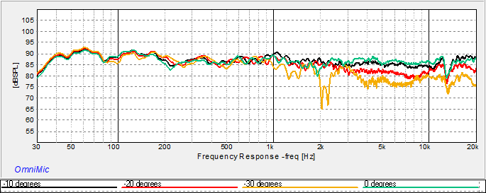
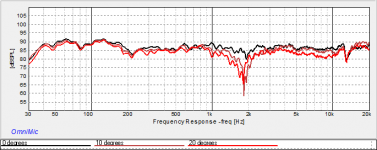
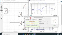
Measured the woofers look like this:
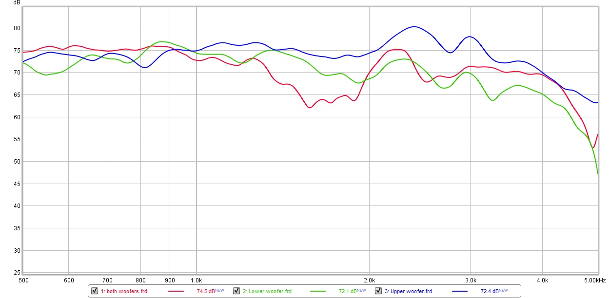
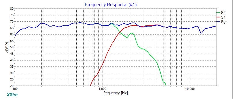
The both woofers running simultaneously have a big dip between 1.5 and 2k that is affecting speaker with the original crossover:
And yes, these are way HOT to my ears!
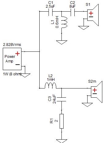
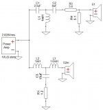
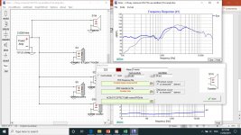
Here's the original crossover:
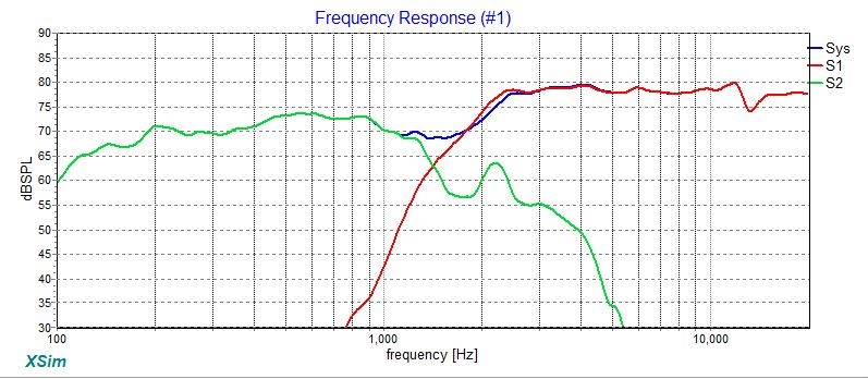
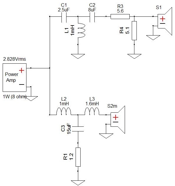
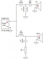
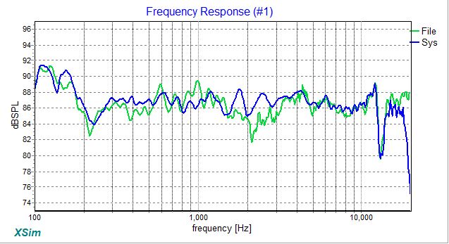
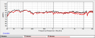
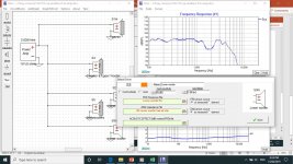
My solution to this is as follows:
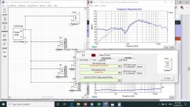
The result is much improved:
What I am keen to know then is if the woofer lobing can be effectively fixed with this crossover or am I just optimising at the measured distance? Put another way, is the dual woofer arrangement still causing problems that may not be evident in my crossover simulated response?
DXO attached for reference.
Thanks!
Dear Mr Waslo and all,
I have a very nice pair of Klipsch KG 5.5's that I want to improve. These are a TWW system; horn loaded dome tweeter with a pair of 10"woofers in a two way arrangement.
I understand that dual woofers in a two way means lobing in the vertical axis.
My question then is; is it possible to improve the system keeping the 2 way configuration through the crossover?
Some data attached to show my approach:
Measured the woofers look like this:
The both woofers running simultaneously have a big dip between 1.5 and 2k that is affecting speaker with the original crossover:
And yes, these are way HOT to my ears!
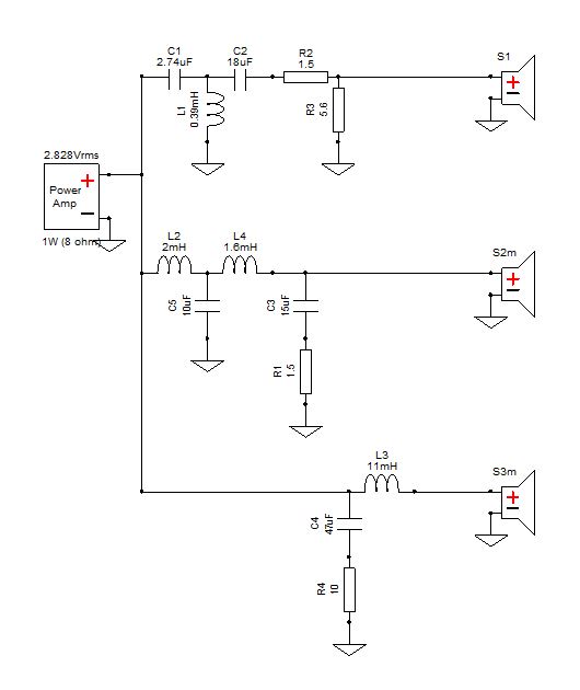
Here's the original crossover:
My solution to this is as follows:
The result is much improved:
What I am keen to know then is if the woofer lobing can be effectively fixed with this crossover or am I just optimising at the measured distance? Put another way, is the dual woofer arrangement still causing problems that may not be evident in my crossover simulated response?
DXO attached for reference.
Thanks!
Attachments
-
 KG woofer comparison.jpg121.4 KB · Views: 1,411
 -
 KG 5.5 XSim new crossover graph.jpg109.6 KB · Views: 1,462
 -
 KG 5.5 XSim new crossover schematic.jpg59.3 KB · Views: 1,381
 -
 KG 5.5 XSim original crossover schematic.jpg44.7 KB · Views: 1,337
 -
2 Way Crossover.dxo113 KB · Views: 119
-
 KG 5.5 XSim original crossover graph.jpg106.6 KB · Views: 1,413
Last edited:
Hello Mazza.
Just throwing out an idea. Any problem with turning the system into a 2.5 way? Second woofer closer to the floor gets a low pass?
Just throwing out an idea. Any problem with turning the system into a 2.5 way? Second woofer closer to the floor gets a low pass?
your new XO looks a 1000 times better than the old, in the FR department.
How about the step response and the impulse with the new XO, how does that look?
How about the step response and the impulse with the new XO, how does that look?
I'd go with what mwmkravchenko suggests, look into a 2.5way. What you suggest with your circuit to attenuate the very hot tweeter will probably be a great improvement, but your woofer null will be only as projected toward that one angle your mic is set to pick up, but I can almost guarantee that most of the in-room energy at those frequencies will be going off toward other angles and arrive at you a little later. In some directions, the null will turn into a peak.
your new XO looks a 1000 times better than the old, in the FR department.
How about the step response and the impulse with the new XO, how does that look?
I agree with the looks waaaaayyyy better!😉
KG 5.5 2.5
Gents,
Many thanks for your compliments, but really the credit must go to Mr Waslo for developing the tool set that has made all this so easily possible!
Omnimic and Xsim are like the keys to the candy shop for me!
It was these lovely KG's that got me to this place, intrigued by their sound I set off reading about horns, stumbled upon the massive AK Econowave thread (which I have read in its entirety), branched off to read Dr Geddes work on HOMS (and his spat with Zilch) and OS Waveguides, Wayne Parnams Pi-pad crossover topology, SEOS genesis and all that lovely DIYSG product that is (for me) unobtainium here in Aus. SO its been a multiyear journey to get to this point!
So I guess my attempt at a minimalist upgrade to the KG's was because I wanted to offer this to any other KG owner that wanted to address the gross issues with the standard crossover. So perhaps this attempt might qualify for this?
A side benefit of reading that big AK Econowave thread was that Zilch was asked many times about a TWW and each time he responded with a "I don't do anything but 2 way and TWW won't work". Happily he spoke to why this was and offered links to 2.5 way JBL designs as starters.
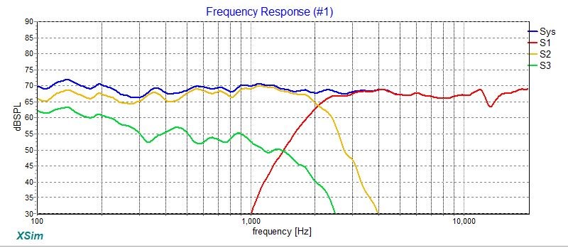
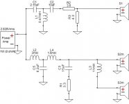
So here's my KG 5.5 2.5 way attempt:
I think that this looks nicer than the two way:
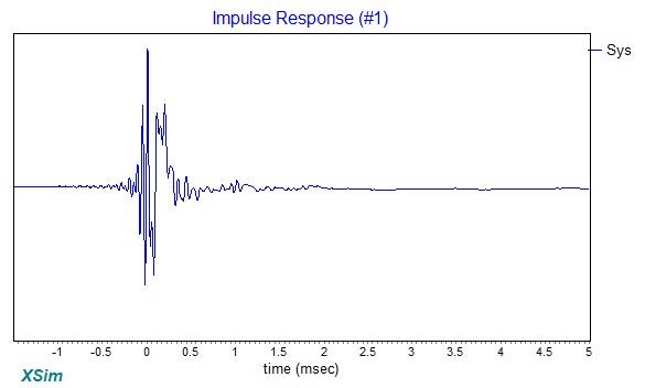
Here's the impulse response. I read with interest about step response which I assume are related and so any help interpreting this is appreciated. Can I use this graph to help set the relative acoustic offset ?
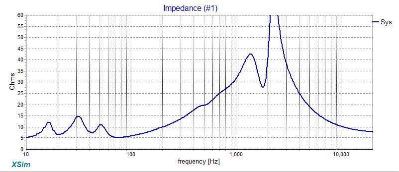
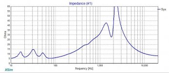
And finally the impedance. My question here is it ok that imp goes high as it does in the treble?
DXO attached for reference.
Again, thank you! 😀
Gents,
Many thanks for your compliments, but really the credit must go to Mr Waslo for developing the tool set that has made all this so easily possible!
Omnimic and Xsim are like the keys to the candy shop for me!
It was these lovely KG's that got me to this place, intrigued by their sound I set off reading about horns, stumbled upon the massive AK Econowave thread (which I have read in its entirety), branched off to read Dr Geddes work on HOMS (and his spat with Zilch) and OS Waveguides, Wayne Parnams Pi-pad crossover topology, SEOS genesis and all that lovely DIYSG product that is (for me) unobtainium here in Aus. SO its been a multiyear journey to get to this point!
So I guess my attempt at a minimalist upgrade to the KG's was because I wanted to offer this to any other KG owner that wanted to address the gross issues with the standard crossover. So perhaps this attempt might qualify for this?
A side benefit of reading that big AK Econowave thread was that Zilch was asked many times about a TWW and each time he responded with a "I don't do anything but 2 way and TWW won't work". Happily he spoke to why this was and offered links to 2.5 way JBL designs as starters.
So here's my KG 5.5 2.5 way attempt:
I think that this looks nicer than the two way:
Here's the impulse response. I read with interest about step response which I assume are related and so any help interpreting this is appreciated. Can I use this graph to help set the relative acoustic offset ?
And finally the impedance. My question here is it ok that imp goes high as it does in the treble?
DXO attached for reference.
Again, thank you! 😀
Attachments

Last edited:
Hoping for some help on improving the vertical off axis with Xsim please.
So I built the 2.5way. I did the driver offset alignment as per Bill's nice post #389 and everything lined up great. Measurements all outside, enclosure about 1.2m off the ground with Omnimic & 5ms gate.
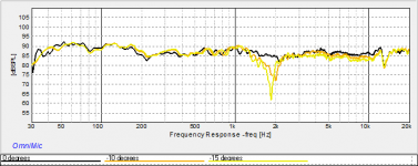
On axis modelled vs measured:
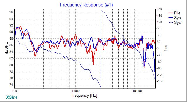
I was not happy to see that dip just below 2khz.
Measuring upwards: 😡
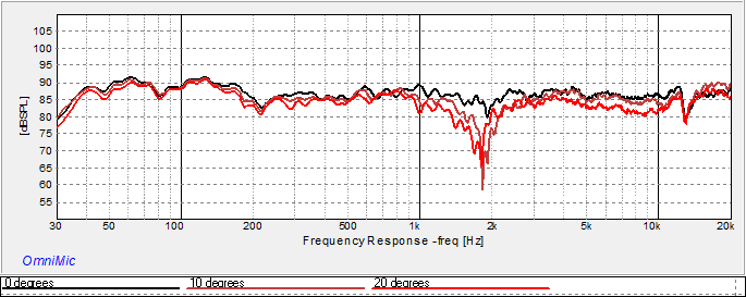
Measuring downwards:
Downwards is much better! But I don't listen sitting on the floor 😱 So I'm thinking do I have the lobe tilted? 😕
So I reversed the tweeter.
Modelled vs tweeter inverted:
Tweeter reversed upward:
Tweeter reversed downward:
I based the 0.5 of my crossover design on the JBL Everest DD66000 which has its woofers in a 0.5 arrangement and added C4 & R4 to flatten the impedance.
I'm sure I'm missing something here!
Help please!
So I built the 2.5way. I did the driver offset alignment as per Bill's nice post #389 and everything lined up great. Measurements all outside, enclosure about 1.2m off the ground with Omnimic & 5ms gate.
On axis modelled vs measured:
I was not happy to see that dip just below 2khz.
Measuring upwards: 😡
Measuring downwards:
Downwards is much better! But I don't listen sitting on the floor 😱 So I'm thinking do I have the lobe tilted? 😕
So I reversed the tweeter.
Modelled vs tweeter inverted:
Tweeter reversed upward:
Tweeter reversed downward:
I based the 0.5 of my crossover design on the JBL Everest DD66000 which has its woofers in a 0.5 arrangement and added C4 & R4 to flatten the impedance.
I'm sure I'm missing something here!
Help please!
Attachments
-
 Vertical Downwards.png13.2 KB · Views: 802
 -
 Vertical Upwards.png12.2 KB · Views: 789
 -
 Modelled vs tweeter reversed measured.jpg57.6 KB · Views: 794
 -
 Tweeter Inverted Vertical Upwards.png11.5 KB · Views: 793
 -
 Tweeter Inverted Vertical Downwards.png11.6 KB · Views: 800
 -
2.5way crossover V0.21 (.5 to amp).dxo170.6 KB · Views: 123
-
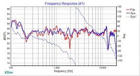 Modelled vs measured.jpg61.3 KB · Views: 800
 -
 2.5way V0.21Circuit.jpg25.3 KB · Views: 835
Last edited:
Looking a lot better. So you have a semi-anechoic measurement 340/1.2= roughly down to 300 hertz. And decent to around 150 hertz if you calculate the bounce time to your microphone.
May I ask if any of the graphs posted are in room?
Because you are putting an awful lot of work into this and you should be actually making adjustments that incorporate the floor and ceiling bounce that will take place in your listening room.
If you have stands, use them. If this is a floor stander then situate them as you plan on using them.
I applaud your choice of a gentle downward taper in the response. Works for me! Been doing it for years.
Are your graphs at 1/24th octave resolution?
You can work with XSim to try to find what's wrong. Provided everything is the same as entered (mic and it's position, reflective surfaces around the measurement area, drivers' behavior, component values) there's no reason why the results shouldn't be a direct match with the modeled other than from environmental noise. So, try to figure out what's different by playing with values in XSim to try to get to what the measured result is.
I'd guess that the differences below about 1200Hz are due to something different in the area, a floor bounce perhaps or something off a wall, or a chair nearby maybe? Those are a dB or less, so I wouldn't get too worried about them anyway if it were mine.
The 8dB suckout is happening at about the crossover point between the tweeter and the upper woofer so the first thing to check is whether the relative delay between those were determined correctly. If you enter a delay value for the tweeter of -0.8 inches, then the curve starts to look more like it measured. -0.8 inches would mean that the simulated tweeter is 0.8" too close to the mic (relative to the upper woofer), so moving the mic downwards (delay more positive, or 0) would be in the right direction (tweeter further from the mic). I don't think that's the difference (or at least not all of the difference) though because the bit at around 3kHz in the 'modeled' result drops a couple of dB if the delay is changed that much but that didn't seem to happen in the 'measured' result.
Other things that seem to go in the right direction are if C2 were closer to 9uF than the modeled 18uF, or if C5 were closer to 13uF than the modeled 10uF. Maybe check those parts with what you used to measure the driver impedances? [And on the subject of those impedances, probably not related to the 2kHz issue, but... ---why do the driver impedances of the two woofers look so different in the bass, aren't they the same type?? The S2 impedance looks very weird with three 'humps' rather than one or two. Might be an interraction between the two of them in the box since they will be strongly coupled].
Another possibility could be interractions between the various inductors. How far are they from each other? If they were to "talk" to each other through fields, very odd things could happen.
Gents, many thanks for your very helpful replies.
Taking a step back first, I did build and measure the 2way option first and it worked out quite well for only my fourth full design with XSim, I think.
All measurements are outside in my back yard both for initial driver measurements and then a few weeks later for the system with this crossover. Same height off the ground, same position in the back yard. With the Omnimic fast sweep running I set the level to 2.8 volts. These speakers are quite efficient and at this level all of my neighbours were messaging me asking what the strange noise was! I applied as many tips as I could from Jeff Bagby's whitepaper for measuring as possible.
I have measured the KG's drivers in 6 different settings ranging from indoors, inside my workshop and then incrementally moving out into the back yard, each time doing full 0-90 degree horizontal polars. It was clear that even with 5ms gating the response got smoother and more repeatable the further outdoors I went.
So do I need to redo my measurements in my final listening room?
All graphs are with zero smoothing. I feel this gives greatest resolution. Even 24db/oct seems to obscure a fair amount of detail. Am I ok in doing this unsmoothed?
I will go back and double check this.
I will do this. I check all my parts with a nice multimeter that has inductance and capacitance measuring ability. I think I will use the DATS V2 that I used for the ZMA to verify the multimeter's measurements. Thanks for the tip.
Yes, I did do a double take when the DATS returned the triple hump and remeasured to only get the same result. I will pull them and measure each woofer outside of the box to isolate any individual driver issue. I figured that the triple hump was a consequence of the second woofer's interaction.
Bill, THANK YOU for taking the time to pay such close attention to my design and getting right under the hood here! Your time and support is VERY HIGHLY APPRECIATED!
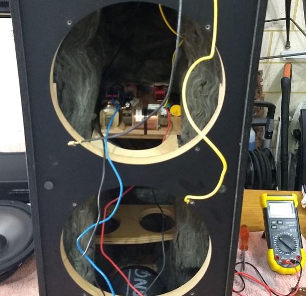
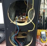
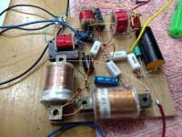
I set out the inductors so as they are all at right angles to each other. Does this look OK?
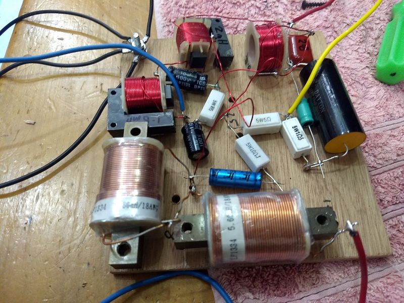
Now looking at this I realised that my inductors are going to be right under the upper woofers magnet, perhaps this is a problem? 😕
THANK YOU!!!!! 😀
Taking a step back first, I did build and measure the 2way option first and it worked out quite well for only my fourth full design with XSim, I think.
May I ask if any of the graphs posted are in room?
All measurements are outside in my back yard both for initial driver measurements and then a few weeks later for the system with this crossover. Same height off the ground, same position in the back yard. With the Omnimic fast sweep running I set the level to 2.8 volts. These speakers are quite efficient and at this level all of my neighbours were messaging me asking what the strange noise was! I applied as many tips as I could from Jeff Bagby's whitepaper for measuring as possible.
I have measured the KG's drivers in 6 different settings ranging from indoors, inside my workshop and then incrementally moving out into the back yard, each time doing full 0-90 degree horizontal polars. It was clear that even with 5ms gating the response got smoother and more repeatable the further outdoors I went.
So do I need to redo my measurements in my final listening room?
Are your graphs at 1/24th octave resolution?
All graphs are with zero smoothing. I feel this gives greatest resolution. Even 24db/oct seems to obscure a fair amount of detail. Am I ok in doing this unsmoothed?
the first thing to check is whether the relative delay between those were determined correctly.
I will go back and double check this.
Maybe check those parts with what you used to measure the driver impedances
I will do this. I check all my parts with a nice multimeter that has inductance and capacitance measuring ability. I think I will use the DATS V2 that I used for the ZMA to verify the multimeter's measurements. Thanks for the tip.
why do the driver impedances of the two woofers look so different in the bass, aren't they the same type?? The S2 impedance looks very weird with three 'humps' rather than one or two. Might be an interraction between the two of them in the box since they will be strongly coupled
Yes, I did do a double take when the DATS returned the triple hump and remeasured to only get the same result. I will pull them and measure each woofer outside of the box to isolate any individual driver issue. I figured that the triple hump was a consequence of the second woofer's interaction.
Bill, THANK YOU for taking the time to pay such close attention to my design and getting right under the hood here! Your time and support is VERY HIGHLY APPRECIATED!
Another possibility could be interactions between the various inductors. How far are they from each other? If they were to "talk" to each other through fields, very odd things could happen.
I set out the inductors so as they are all at right angles to each other. Does this look OK?
Now looking at this I realised that my inductors are going to be right under the upper woofers magnet, perhaps this is a problem? 😕
THANK YOU!!!!! 😀
Attachments
Last edited:
Absolutely. Smoothing can always be added in in XSim. I only use smoothing during measurement when I'm not going to save the file and am trying to see through lots of 'grass'.All graphs are with zero smoothing. I feel this gives greatest resolution. Even 24db/oct seems to obscure a fair amount of detail. Am I ok in doing this unsmoothed?
Yes, I did do a double take when the DATS returned the triple hump and remeasured to only get the same result. I will pull them and measure each woofer outside of the box to isolate any individual driver issue. I figured that the triple hump was a consequence of the second woofer's interaction.
Try shorting out the terminals on the woofer not being measured. It won't perfectly take out the effect of interractions, but will be closer.
I set out the inductors so as they are all at right angles to each other. Does this look OK?
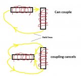
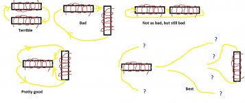
Not really. That may not be the problem, but I can see a number of possible interractions in the layout. Try to look at inductors as if they are trying to be transformers (which is what you're trying to prevent). When they share a core (even with some air gaps) or when a dominant shared magnetic path can be traced through their axes (and that doesn't have to travel too long), they can talk to each other. If close together, they need to be not only at right angles but also symmetrical. If they are done that way, then there is no preferential magnetic path through both windings so the lines going over equal but opposite paths would cancel out (lower picture). To make that happen, they have to be at right angles, but not in anything that might approach sitting "end to end" (like in the upper picture).
I traced out some likely shared field lines between close inductors in your photo (different colored lines scribbled on the photo):
Distance between inductors is your friend, maximize that and then any that still have to be close should be arranged to be perpendicular and symmetric as possible. Ferrous cored inductors couple most strongly and there are three of them in your layout that sit virtually end-to-end!
Probably not. It would be preferable to not have iron or ferrite cored inductors in a strong magnetic field since that might tend to make the cores saturate a little earlier when driven. The air core inductors probably don't care too much unless they are REALLY close to magnetic materials (which might alter their inductance). If you have a choice, get them away from magnets and other large metal pieces but it's probably not a show stopper.Now looking at this I realised that my inductors are going to be right under the upper woofers magnet, perhaps this is a problem? 😕
Attachments
Last edited:
All measurements are outside in my back yard both for initial driver measurements and then a few weeks later for the system with this crossover. Same height off the ground, same position in the back yard. With the Omnimic fast sweep running I set the level to 2.8 volts. These speakers are quite efficient and at this level all of my neighbours were messaging me asking what the strange noise was! I applied as many tips as I could from Jeff Bagby's whitepaper for measuring as possible.
I have measured the KG's drivers in 6 different settings ranging from indoors, inside my workshop and then incrementally moving out into the back yard, each time doing full 0-90 degree horizontal polars. It was clear that even with 5ms gating the response got smoother and more repeatable the further outdoors I went.
So do I need to redo my measurements in my final listening room?
Bill's answer is spot on. As long as your measurement conditions are known and entered into the software you are fine.
All graphs are with zero smoothing. I feel this gives greatest resolution. Even 24db/oct seems to obscure a fair amount of detail. Am I ok in doing this unsmoothed?
You are doing very well actually. The peaks looked like 1/24th octave resolution. So you are creating a very god crossover.
Bill has loads more crossover experience than I have. And his advice is pretty much what I thought about to. Only he is more familiar with his program ( I wonder why???)
Your inductor placement is great until you are sitting in the stray magnetic field of your woofer. Without getting into possible effects of mutual coupling with the stray magnetic field of a woofer motor it's best to keep them a about 10cm away from the woofer motor parts. Generally there is a bit of stray magnetic field at the sides and about 45 degrees off the central axis of the back plate.
Would anyone of your guys or ladies like to run this program and design a crossover for me. Just message me and I’ll give you my info on the drivers and size of the speaker cab . I’m only able to do things on my iPhone 8+ as I have not setup any of my computers sense I’ve moved into my new home. That’s on the end of a very long list of to-do things right now. Lol
Thanks. People
Carl
Thanks. People
Carl
carlthesis, with few exceptions (some Dayton drivers), there's not enough info on a data sheet or manufacturer supplied graph to simulate and design a crossover. You nearly always have to have measurements of actual drivers, at the correct relative distance from the listener (how much closer or farther from the mic/listener is the tweeter than the midrange, etc), on the actual baffle. A rough crossover that will at least keep the drivers from getting blown up (maybe) can be done, but it is likely to have some peaks and dips in places particularly in the sensitive lower treble.
Breaking it down....
Dear Bill, Mark etal,
Many thanks for your encouragement and ongoing support here. Really appreciated.
I will try to systematically work through your suggestions to see if I can isolate the root case. Please hang in here with me!
This was very practical and helpful thank you Bill. I had a long play with my off sets and figured I needed to go back to the start.
So I made a new .dxo and added in my three drivers and also a driver for each pair's combined .frd.
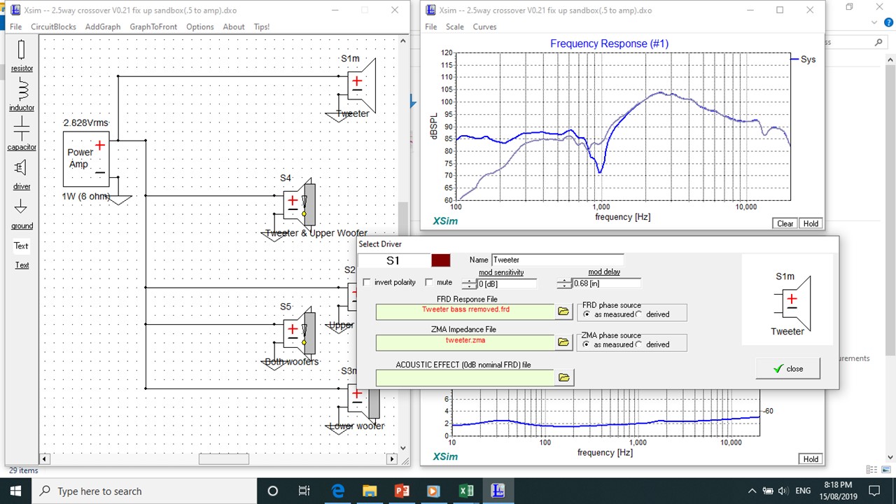
So, looking at the tweeter and upper woofer I cannot get complete alignment.
Looking back to my built design, if add the additional 0.8in delay to the tweeter I get the following overlay which doesn't look great: 😕
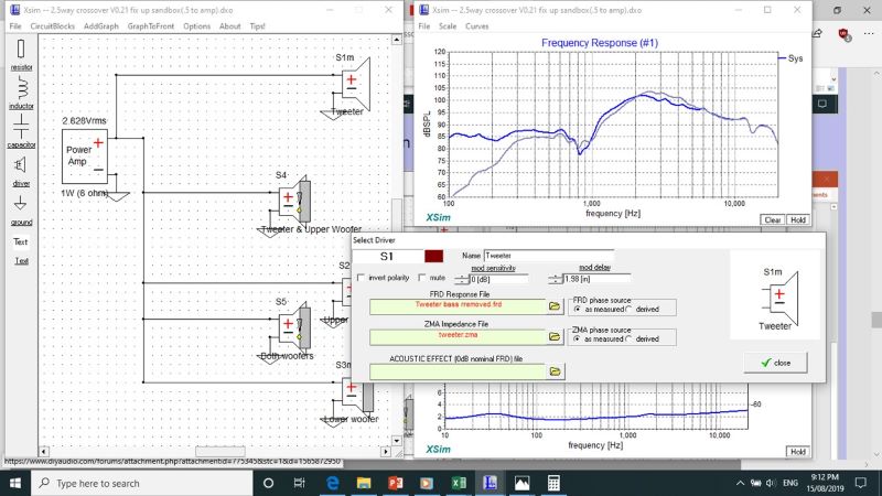
However I can get alignment from 2khz and above with 0.68in on the tweeter:
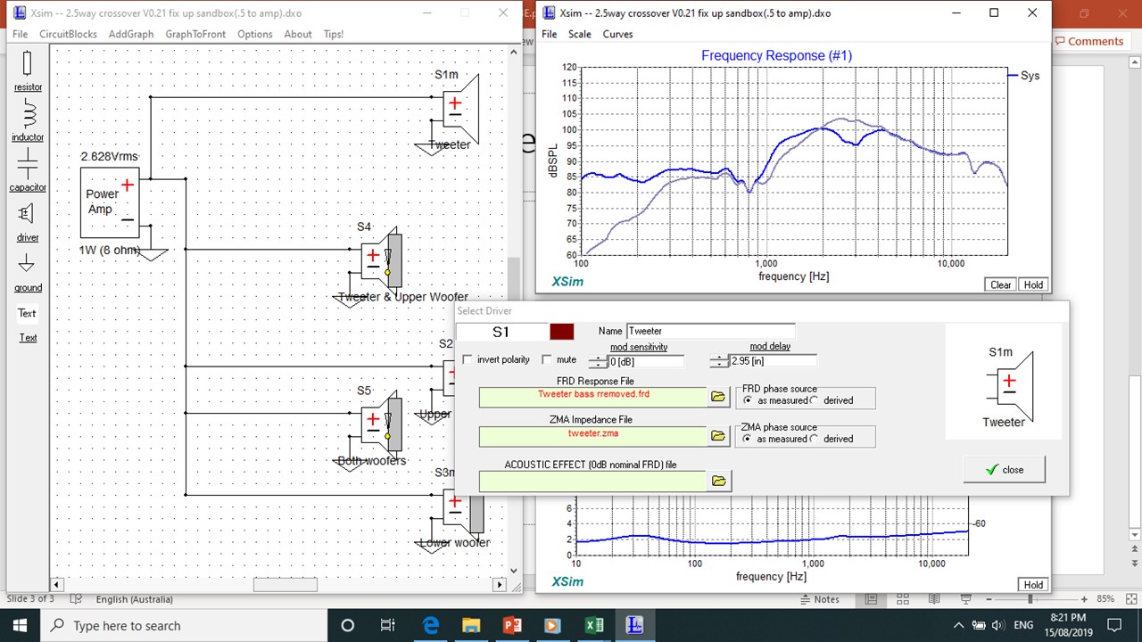
About 1khz to 4khz with 1.16in on the tweeter:

And at 800kz in that little dip with 2.95in
So my questions are:
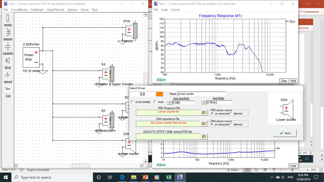
The pair of woofers on the other hand align beautifully with 2.98 on the lower woofer (zero on the upper woofer):
I went back and remeasured my impedances shorting out the woof not being measured and this worked well - new ZMA's have a typical double hump and are in use here in the DXO attached.
Incidentally I measured my woofers FRD with the other woofer shorted. At 2.8v the woofer not being measured was still jumping around a bit in sympathy, even when shorted, and so, standing to the side of the enclosure, I gently pressed on the woof not being measured with my fingers to further damp its cone.
DXO attached, thank you again!
Dear Bill, Mark etal,
Many thanks for your encouragement and ongoing support here. Really appreciated.
I will try to systematically work through your suggestions to see if I can isolate the root case. Please hang in here with me!
You can work with XSim to try to find what's wrong.
The 8dB suckout is happening at about the crossover point between the tweeter and the upper woofer so the first thing to check is whether the relative delay between those were determined correctly. If you enter a delay value for the tweeter of -0.8 inches, then the curve starts to look more like it measured. -0.8 inches would mean that the simulated tweeter is 0.8" too close to the mic (relative to the upper woofer), so moving the mic downwards (delay more positive, or 0) would be in the right direction (tweeter further from the mic).
This was very practical and helpful thank you Bill. I had a long play with my off sets and figured I needed to go back to the start.
So I made a new .dxo and added in my three drivers and also a driver for each pair's combined .frd.
So, looking at the tweeter and upper woofer I cannot get complete alignment.
Looking back to my built design, if add the additional 0.8in delay to the tweeter I get the following overlay which doesn't look great: 😕
However I can get alignment from 2khz and above with 0.68in on the tweeter:
About 1khz to 4khz with 1.16in on the tweeter:
And at 800kz in that little dip with 2.95in
So my questions are:
- any of these possible proxy Z off sets for my design?; or
- maybe I've done something wrong/overlooked/missing something here?; or
- has my measurement failed and I need to restart?
The pair of woofers on the other hand align beautifully with 2.98 on the lower woofer (zero on the upper woofer):
Try shorting out the terminals on the woofer not being measured. It won't perfectly take out the effect of interactions, but will be closer.
I went back and remeasured my impedances shorting out the woof not being measured and this worked well - new ZMA's have a typical double hump and are in use here in the DXO attached.
Incidentally I measured my woofers FRD with the other woofer shorted. At 2.8v the woofer not being measured was still jumping around a bit in sympathy, even when shorted, and so, standing to the side of the enclosure, I gently pressed on the woof not being measured with my fingers to further damp its cone.
DXO attached, thank you again!
Attachments

Last edited:
Measurements...
So I had a minor brain fart - realised I have 6 sets of measurements!
So I went back to measurement set 5.
Quick and dirty, I add three drivers, tweeter, upper woofer and combined Tweeter/upper woofer.
Hold the combined driver FRD, unmute tweeter and upper woofer and add a smidge of delay to the tweeter and we get.....
Conclusion - my sixth set of measurements are wonky? 😡
Attachments

Thank you very much for this brilliant piece of software! This will make the tuning of my MF/HF horn crossover a breeze.
Cure to "Failed to open" error
XSim is a great piece of software and I can confirm that when using Holm Impulse for acquiring the FRD-measurements, simulation results are very consistent, even down to setting driver offsets with delay.
It seems that on non-English PC systems, which use a different decimal point (comma here in Germany), XSIM gets confused when it saves data.
On reopening it crashes with the Open failed, division by zero message.
I compared one of the examples with one of mine and found that the culprit is the component values being saved in the dxo file with comma as decimal point.
A simple search and replace (search ",", replace with ".") makes the file palatable for Xsim again.
Maybe this vulnerability could be changed in the sw code. Thanks anyway, Bill!

- Home
- Design & Build
- Software Tools
- XSim free crossover designer