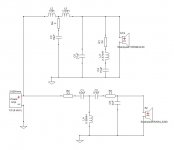
I been working with jReave on designing a 2way floorstander through various software tools available. This has been quite the learning experience. Thought I would post where I am at with the crossover design. See attached Xsim files. Please be kind.🙂
Best Regards,
Rich
Best Regards,
Rich
Attachments
Nice looking! GND symbols are free you know. 😀
Just in general, the 18W/4434 has 3dB more output, so it often makes a better level match for the tweeter.
The speaker is too flat and will sound dry and bright. Use the B&K curve or something like it as your target.
Not sure if this would work for you, but instead of R3/C6 try a very small inductor. 0.1mH or so. It may take the edge off.
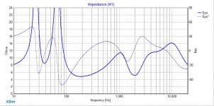
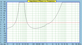
Those high impedance peaks can be equalized with a 60 to 100 Ohm resistor in parallel with the inputs, with only a minor degradation of the minimum.
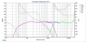
I am impressed your FR curves are so accurate but no one gives prizes for precisely matching a particular named filter curve. FR and phase matching are much more important than matching the exact curve profiles which brings me to the next point. The tweeter I have is much smoother and requires much less equalization. I'm a little surprised at the number of tweeter parts as well as the tweeter impedance profile. Both seem complicated. Do you really need an LR4?
Best,
Erik
Just in general, the 18W/4434 has 3dB more output, so it often makes a better level match for the tweeter.
The speaker is too flat and will sound dry and bright. Use the B&K curve or something like it as your target.
Not sure if this would work for you, but instead of R3/C6 try a very small inductor. 0.1mH or so. It may take the edge off.
Those high impedance peaks can be equalized with a 60 to 100 Ohm resistor in parallel with the inputs, with only a minor degradation of the minimum.
I am impressed your FR curves are so accurate but no one gives prizes for precisely matching a particular named filter curve. FR and phase matching are much more important than matching the exact curve profiles which brings me to the next point. The tweeter I have is much smoother and requires much less equalization. I'm a little surprised at the number of tweeter parts as well as the tweeter impedance profile. Both seem complicated. Do you really need an LR4?
Best,
Erik
Last edited:
Thanks Erik,
That's the input I'm looking for. I'm not pretending to know everything about this stuff (just trying to learn as I go and have fun).🙂. The LR4 crossover topology was suggested by jReave to integrate with the chosen drivers. It is similar to a design Troels Gravesen tested in building the Discovery W18. Please keep in mind; I was not posting something I considered a completed design. I felt it would be better to seek advice at this stage before wasting countless hours. You mentioned the R3/C6 and it was used in an effort to tame down the upward spike in the 15k region. The cap seemed to work better then the coil but I will try the value you suggested as well. I knew the impedance peaks would need to be addressed but was not sure of method to use to bring it to a better load for the amplifier. I appreciate the help in pointing me in the right direction!
Best Regards,
Rich
First, it's definitely looking better.
Second, are you still simming with the same tweeter?
Next, you need to understand the difference between electrical and acoustic xo's. What I was suggesting was 4th order acoustic and this means that the rolloff slope is at about 24dB/octave. However, and this is the important thing, you don't need 4th order electrical filters to achieve it. Not even 3rd order necessarily. In fact it's typically easy to produce 4th order acoustic with 2nd order electric when you also take into account the natural rolloff (often about 12dB/octave) of the driver.
So in other words, the target curves are the targets for the drivers' acoustic responses and the fewer parts you need to achieve them - and keep your phase aligned - the better.
The impedance peaks are unconcerning - that is absolutely typical of any woofer in a ported alignment that hasn't worried about using an impedance compensation filter which is the majority of commercial speakers out there. The phase that drops below -60* at about 80Hz is more concerning, but I expect that will disappear when you reduce the number of parts on your woofer filter.
I'm still also wondering about your woofer file. With a sensitivity of about 88dB on the woofer, losing about 6dB to baffle step should net you a speaker level somewhere around 82dB to 84dB but you are still up around 87dB. Why don't you attach a quick diagram of your front baffle with dimensions and driver positions and then I can play along and then have something to compare your work to.
Thanks jReave,
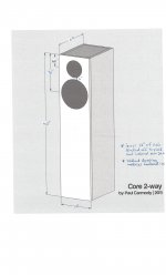
The tweeter simmed is the SS D2604/8330 model. I forgot to change it in the diagram (sorry). Yea, I remember now your point on natural driver roll off to achieve steeper slopes from prior posts. With the LR4 topology, I can see how it can sound dry and bright as Erik described. I will work on getting a file of baffle dimensions to you here directly. I have used a printed version from Paul Carmody's Core build that has been changed slightly to be somewhat taller. I'll put something together in file form and get that sent out (ASAP).🙂
Best Regards,
Rich
I don't think Eric was saying that it's the xo topology will make it dry and bright but rather the overall FR being too flat. However, I'm not in complete agreement with this. It may be true. It may not. You may like it like that. You may not. Because as I think I mentioned before, the on-axis FR isn't the only thing that affects the overall perceived response. Off-axis does too. Again, 1 of the reasons I like PCD a little better for speakers with standard topology.
Hi jReave,
Here is attachment with baffle dimensions/ driver layout as you requested. This process certainly been a learning experience for me and somewhat out of character. Generally, I'm one to sit back and not say much. But, people on this forum are far more positive and that lessens some of the anxiety of putting posts up. Anyhow, I will probably fall down more then I have already in the effort to learn this stuff. I know each person may prefer as certain type of soundstage. To be honest, I'm not sure what I would like best. My suspicions are that several will sound very pleasing but in differing ways. It appears I may need to revisit PCD again. I looked at it awhile back and found it a bit intimidating and therefore opted to go the Xsim route. Again, I really appreciate your patience and help!🙂
Best Regards,
Rich
Attachments
About R3/C6, it's only needed due to the rest of the tweeter filter, I think. I have the same (nearly) tweeters and don't get that peak. 🙂
Take a look at my discussion of the LM-1 here. I'm not claiming to be even a demigod of crossovers, but you are running into issues I don't feel I had. This is more about compare and contrast to create knowledge. Even if you don't like my choices, it will give you a more complete idea of the pros and cons of your own. 🙂
Best,
Erik
Thanks Erik,
That's the input I'm looking for. I'm not pretending to know everything about this stuff (just trying to learn as I go and have fun).🙂. The LR4 crossover topology was suggested by jReave to integrate with the chosen drivers. It is similar to a design Troels Gravesen tested in building the Discovery W18. Please keep in mind; I was not posting something I considered a completed design. I felt it would be better to seek advice at this stage before wasting countless hours. You mentioned the R3/C6 and it was used in an effort to tame down the upward spike in the 15k region. The cap seemed to work better then the coil but I will try the value you suggested as well. I knew the impedance peaks would need to be addressed but was not sure of method to use to bring it to a better load for the amplifier. I appreciate the help in pointing me in the right direction!
Best Regards,
Rich
Last edited:
I don't think Eric was saying that it's the xo topology will make it dry and bright but rather the overall FR being too flat. However, I'm not in complete agreement with this. It may be true. It may not. You may like it like that. You may not. Because as I think I mentioned before, the on-axis FR isn't the only thing that affects the overall perceived response. Off-axis does too. Again, 1 of the reasons I like PCD a little better for speakers with standard topology.
jReave,
That's right. My comments about the FR being too flat were not about filter types but choices in crossover design and level matching. you are doubly right about it being a personal taste. 🙂
I don't have a link, but there's lots written on why flat is rarely the right choice in anything but an anechoic room. Of course, this also depends on how you are measuring. If you are measuring quasi-anechoically then your room gain may prevent some of this naturally.
Also, I've seen some speakers that measure flat on axis, but near perfect B&K curve at 20-30 degrees, which allows for you to match the speakers to personal taste based on toe-in. To plan for this you'll need those off-axis measurements though. 🙂 And that may or may not burst your filter types. 😀
Best,
Erik
Attachments
Last edited:
Thanks for that.
Something to consider: with that size floorstander and with the extra volume on the bottom, you can actually increase your internal volume if you want to. Zaph's specs allow you to go up to 48L.
Let's work on your file creation for a moment. Response Modeler's impedance sim is good for the bottom part of the graph (ie. the box effects) but if you read Jeff's blurb on his download page, you'll learn that it may or may not be a little off in the rest of the graph. So here's what you should do:
- trace the woofer's measured impedance from about 100Hz up (or the whole thing, whatever is easiest). Might as well stick with Zaph's
- input the TS and box data into the Impedance section as per Carmody to get your blue impedance curve
- now use the "Import ZMA File to Modify" button to import your traced impedance file
- turn the "Overlay Imported ZMA" button ON.
- if the curves above about 100Hz do not overlay exactly, use the "Le Expon." and the "Le Coeff." spinners to do so
- if those don't do the trick, use the "Minimum Phase Equalization Modules" to fine tune your results
This is similar to what you are doing with the FR curve when you put the driver in a box: you want the FR above about 200Hz to be the same as measured and below that to be the in-box sim. Same for the impedance. You want the z above about 100Hz to be the same as measured and below that to be the in-box sim. This can be an important step because sometimes the simmed z can be out by a fair amount. And don't forget, it's the impedance that the xo components interact with to change the FR.
Might not hurt to post your raw woofer file with box and baffle effects included. You can post the graph or the actual file (change the file extension to .txt in order to attach frd or zma files). I want to double check your process here before you start working on the xo.
Eric, the important distinction here is that those house curves are for measures taken from the listening position, ie. including in-room effects and that is not what any of the popular xo sim programs are doing. We are generally not including all the boundary and room gain augmentation and thus targeting a flatter curve is appropriate.
Now once you take that speaker and measure it in room at the listening position, you are indeed likely to end up with a curve similar to what you posted, rising in the bottom end. But of course rooms are different and like you say, so is personal taste, so starting with a simmed flat curve, then taking power response into account and then putting them into the room to start voicing the bass and treble balance is the model that I am working with here.
YMMV of course.
Thanks jReave,
I will work on those items later this afternoon. For now, I need to get a little work done on the Golf Course. Snow has melted off!
Best,
Rich
I will work on those items later this afternoon. For now, I need to get a little work done on the Golf Course. Snow has melted off!
Best,
Rich
Eric, the important distinction here is that those house curves are for measures taken from the listening position, ie. including in-room effects and that is not what any of the popular xo sim programs are doing. We are generally not including all the boundary and room gain augmentation and thus targeting a flatter curve is appropriate.
Now once you take that speaker and measure it in room at the listening position, you are indeed likely to end up with a curve similar to what you posted, rising in the bottom end. But of course rooms are different and like you say, so is personal taste, so starting with a simmed flat curve, then taking power response into account and then putting them into the room to start voicing the bass and treble balance is the model that I am working with here.
YMMV of course.
And that's why I use far field to measure the FRD that I import to XSim. 😀 I get built-in far field response curves, and those ain't flat! (Sorry, too much Walking Dead, starting to type with a southern drawl).
One bit of heresay from both Lee Taylor ( Taylor Speakers ) and Madisound, is that at least with Leap, targeting a flat response leads to a design they really don't really like. I'm not sure if that's something unique to Leap (Lee thought it was) or just the overall process. Lee particularly distrusts Leap for this reason.
Best,
Erik
Last edited:
I just wanted to share an alternate approach suitable perhaps only for a 2 way. I may miss some things, but it's accurate. It relies on good tools to make it all work, and I find it violently free of frustration. 😀 😀 😀
1. Get the actual drivers you plan to use in your cabinet. It's really good if you can find an existing kit and make sure their cabinet size and results were similar to your own desires.
2. Measure T/s with DATS. Yes, there are free alternatives, but man, for $99 I just press "GO" and it works. $50 if bought with OmniMic. By the time you are done ordering parts and calibrating sound cards I'm putting drivers in a box. 🙂 Or at least that's my level of expertise with DIY electronics.
3. Simulate cabinet in WinISD and choose your cabinet size. I find it very useful when trying to choose among several Dayton pre-built cabinets.
4. Build cabinet (or in my case, order them, and route circles).
5. Measure woofer impedance in cabinet. (Tweeter is more or less irrelevant where you measure it. It's possible the baffle it's on could affect the results, but if so it's minor)
6. Measure far field (3' ~= 1M) FR of tweeter and woofer in cabinet.
7. Import far field FR
8. Import Driver Z from DATS.
9. Calculate driver offsets.
10 - Design crossover.
Last edited:
Erik,
Thanks for sharing. That is certainly a viable approach and one I'm soon to explore.
Best Regards,
Rich
Thanks for sharing. That is certainly a viable approach and one I'm soon to explore.
Best Regards,
Rich
Hi jReave,
Hopefully, I've done this right in attaching the Response Modeler info in the manner you requested. Just a couple items I'm not totally sure of:
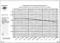
1) I traced the attached chart from Zaph. Is that the correct one?
2) I noticed Zaph has vas @ 4.92 l and Scanspeak has it at 19.5 l. Does that discrepancy really matter?
Best Regards,
Rich
Hopefully, I've done this right in attaching the Response Modeler info in the manner you requested. Just a couple items I'm not totally sure of:
1) I traced the attached chart from Zaph. Is that the correct one?
2) I noticed Zaph has vas @ 4.92 l and Scanspeak has it at 19.5 l. Does that discrepancy really matter?
Best Regards,
Rich
Attachments
Hi jReave,
Lets try this corrected file. I answered my own question in regards to vas discrepancy. I revisited Zaph blog and low and behold vas showed to be 13.6 l. That certainly made a big difference. I don't know where 4.92 value came from. Looking at to many charts I suppose.🙂
Best,
Rich
Lets try this corrected file. I answered my own question in regards to vas discrepancy. I revisited Zaph blog and low and behold vas showed to be 13.6 l. That certainly made a big difference. I don't know where 4.92 value came from. Looking at to many charts I suppose.🙂
Best,
Rich
Attachments
try a very small inductor. 0.1mH or so. It may take the edge off.
Hi Erik, My HF filter has this although I don't understand why.
Could you please explain what is the purpose of using a very small inductor prior to the driver?
Thank You.
Yup, that would be the correct chart from Zaph.
The file you attached though isn't what I'm looking for. Sorry, maybe I wasn't clear enough in my instructions. What I want is to see what your simulated woofer FR looks like before you start working on the xo. This will be the frd file that you import into XSim. Right now it looks to me like your SPL level is too high.
So you can:
- attach that file (the frd. file extension needs to be changed to txt.) or
- attach an image of the FR in a graph. You could use a chart from XSim before you start on the xo or you could take a screen shot of Response Modeler's top graph (zoom to a more detailed scale), import it into MS Paint and save it as a jpeg or gif. or
- maybe there's another way I haven't thought of yet.....
- Status
- Not open for further replies.
- Home
- Loudspeakers
- Multi-Way
- Xsim Critique Part 2