C1 and C2 on Mute board: Mute - I2S over USB Audio
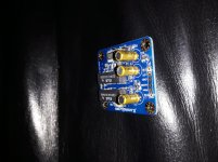
Hi I don't have the mute circuit schema. However, looking at the PCB, it looks like the input signal goes through C1 and C2.
Hi I don't have the mute circuit schema. However, looking at the PCB, it looks like the input signal goes through C1 and C2.
I don’t think so..
Looks like input signal goes between legs of C1 and C2 directly to the relays..
I don’t think so..
Looks like input signal goes between legs of C1 and C2 directly to the relays..
Hi,
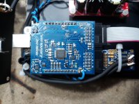
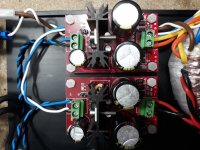
I might be wrong, however looking at these pictures it looks like Rin goes to + of C2, then from - of C2 it goes to the relay. Symmetrically, Lin goes to + of C1, then from - of C1 to the relay. I tried with an Ohmmeter and this seems to be confirmed.
Attachments
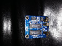
This is double-sided or multi-layer pcb..
There is layer for analog signal, another for power..
Opamp board have relays without signal caps, there is no reason for using them on this..
There is layer for analog signal, another for power..
Opamp board have relays without signal caps, there is no reason for using them on this..
Last edited:
YesThis is double-sided or multi-layer pcb..
In fact Rin and Lin are respectively left and right input signals, and ... they go to C2 and C1 caps. Then from caps to relays. The two pictures are very high res. You can enlarge and double check yourself.There is layer for analog signal, another for power..
I agree. However, this is it.Opamp board have relays without signal caps, there is no reason for using them on this.
In any case, no point continuing arguing on this without a schema. 🙂
In any case, no point continuing arguing on this without a schema. 🙂
I’m not arguing, it is very strange to have cups on signal path without good reason..
You have board, you can easily check is where are cups, on power or signal
Hi,
I have info that those caps are on signal path. They are for safety a guess - i think that Mute circuit connects the output with ground when i2soverusb detects change in sampling rate to avoid pops and clicks. Some output stages do not have output capacitors and it is possible that there would be problems when connected directly to the GND.
I think this could be solved in another way, without those capacitors.
Last edited:
Hi fellows,
It's been a long time since I wrote in forum, sorry about that.All questions asked by mail are answered by Lyuben.
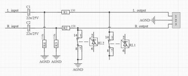
Regarding mute scheme - for C1 and C2 caps - they are put for preventing, if previous stage has DC signal on the output and the stage after mute board works on amplifying 0V DC (i.e. DC amplifier), in order not to get in trouble.
If from the stage before mute, there is no offset, then C1 and C2 caps can be shortened. The mute signal path is parallel on output signal, i.e. AC signal doesn't come through relay. The output signal is shortened in order not to overload the relay also the stage before mute board, there is 150ohm resistor on signal path. This means that even 15Vp-p signal won't overload the relay. There is no interruption on signal path - I did this on purpose. cause I think (and hear) that every one relay on signal path adds its' mark.
I publish the scheme here to be more clear.
For me it will be big relief if my son Lyuben will register here and give answers on my threads. I hope that admins won't mind this.
For those who use DRV603 board - there is no need of mute board, cause the DRV603 op. amp. has embedded mute, which works fine.
Off topic: We have new licensed JLsounds driver from Thesycon and can be downloaded from our website, also there is an update for I2soverUSB v.III board.
Best,
Joro
It's been a long time since I wrote in forum, sorry about that.All questions asked by mail are answered by Lyuben.
Regarding mute scheme - for C1 and C2 caps - they are put for preventing, if previous stage has DC signal on the output and the stage after mute board works on amplifying 0V DC (i.e. DC amplifier), in order not to get in trouble.
If from the stage before mute, there is no offset, then C1 and C2 caps can be shortened. The mute signal path is parallel on output signal, i.e. AC signal doesn't come through relay. The output signal is shortened in order not to overload the relay also the stage before mute board, there is 150ohm resistor on signal path. This means that even 15Vp-p signal won't overload the relay. There is no interruption on signal path - I did this on purpose. cause I think (and hear) that every one relay on signal path adds its' mark.
I publish the scheme here to be more clear.
For me it will be big relief if my son Lyuben will register here and give answers on my threads. I hope that admins won't mind this.
For those who use DRV603 board - there is no need of mute board, cause the DRV603 op. amp. has embedded mute, which works fine.
Off topic: We have new licensed JLsounds driver from Thesycon and can be downloaded from our website, also there is an update for I2soverUSB v.III board.
Best,
Joro
Attachments
Thanks Joro for the schema.
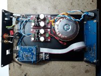
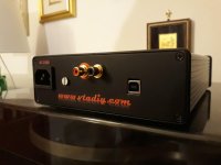
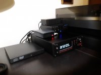
I finally finished my build as well.
It has I2SoverUSB v.III, AK4493 board, DRV603 Filter, OLED control, and dedicated external power supply for USB, and oscillators/reclock/AK4493/filter.
I believe its audio quality is impressive 😱.
I finally finished my build as well.
It has I2SoverUSB v.III, AK4493 board, DRV603 Filter, OLED control, and dedicated external power supply for USB, and oscillators/reclock/AK4493/filter.
I believe its audio quality is impressive 😱.
Attachments
Found the original I2SoverUSB and AK4396 on a box today. Tried to plug it in and play some music using Tidal. To my surprise the board lit up on 96KHz on some Tidal Master recordings...
It was my understanding that you had to have some MQA compatible dac to take advantage of this?
It was my understanding that you had to have some MQA compatible dac to take advantage of this?
Thanks Joro for the schema.
I finally finished my build as well.
It has I2SoverUSB v.III, AK4493 board, DRV603 Filter, OLED control, and dedicated external power supply for USB, and oscillators/reclock/AK4493/filter.
I believe its audio quality is impressive 😱.
Nice layout Giuseppe! I'm saving a pair of pics as reference for future...! 😀
- Home
- Source & Line
- Digital Line Level
- XMOS DSD 384 kHz / 32bit USB