Lucian, may I ask - what is the actual "source voltage" across each LED take-off? In a previous post in this thread a member suggested to another that he place a 5K resistor in series with a standard LED to limit current to your specified 8mA, but 5K seems very high. If the "source voltage" is (say a guess) 3.3V, and your LED has a 2V drop, then the resistor ought to be around 180R in order to limit current to 8mA. However we need the actual "source voltage" to calculate this.
Hi Ian, I presume you're referring to my #1428 post.
You're correct, my reply can be misinterpreted. The resistor value depends on what current you want. 8mA caused real brightness with my leds.
If you really want 8mA, ~180R is the correct value.
I confirm I was using 5k resistor, I wanted the leds very dim.
The Led Vout is around 3.1V (#1124), on my board.
Thank you m.massimo. Yes and thanks for the perfect info. Now I see your post #1124 which I could not have found so easily way-way back in such a long thread otherwise. Cheers.
Hello!
Is there anybody who knows if the WaveIO USB module can be placed under a DAC (maybe 4-5 cm under a DAC pcb) without any problems - soundwise or other -regarding EMI or RF etc.? Maybe some kind of shielding is necessery?
Vidar
Is there anybody who knows if the WaveIO USB module can be placed under a DAC (maybe 4-5 cm under a DAC pcb) without any problems - soundwise or other -regarding EMI or RF etc.? Maybe some kind of shielding is necessery?
Vidar
Lorien - any luck with the new Thesycon drivers for us WaveIO users?I have plans to do it these days because I must reserve some time for this task since there are couple of custom driver I need to build besides WaveIO. Even if I looked into the revision document I'm curious what 'huge' updates are you talking about? 🙂
Do you have to change the software or is it just a matter of putting them on your website?
Thanks Jonathan
How about new drivers ? 2.15 version.
Generic package is online since 31.10.2013 on XMOS webpage.
Generic package is online since 31.10.2013 on XMOS webpage.
Hi Lorien,
I am trying out the UFL connections from wave IO to dddac but this is unsuccesfull now. I have connected data, BCK, LR and GND of the dac to the UFL connectors of wave IO.
Sound is distorted, mostly noise with the music on back ground.
Am I doing something wrong?
Regards,
I am trying out the UFL connections from wave IO to dddac but this is unsuccesfull now. I have connected data, BCK, LR and GND of the dac to the UFL connectors of wave IO.
Sound is distorted, mostly noise with the music on back ground.
Am I doing something wrong?
Regards,
Hi Ss!
Data, LR, and Bck should work. Don't forget to connect ground to H4......and put 3.5 to 5Volts on pin 5 of the bigger connector, next to the Ufl's. This is what the isolator needs to get working!
Ed
Data, LR, and Bck should work. Don't forget to connect ground to H4......and put 3.5 to 5Volts on pin 5 of the bigger connector, next to the Ufl's. This is what the isolator needs to get working!
Ed
Last edited:
Sound is distorted, mostly noise with the music on back ground.
Hi Supersurfer, your comment is very interesting to me cause I've a problem similar to yours.
My WaveIO feeds a TP Opus through uFL. Starting from an indefinite moment a couple of weeks ago (and not related to any circuit change or setting I can remember) I got some very audible distortion, particularly in one channel, but only at multiple of 44.1 and 48, these two sampling rates seem to work correctly.
I tried to swap the dac with a spare board, but nothing, same result.
It's becoming very annoying, cause I've not been successful at isolating the problem.
Last edited:
Hi Massimo,
I am discussing this problem also on the dddac thread, there it is suggested that the load of the dac (I use 4 dacs in parallel) is to big for the wave io, it is suggested to put extra series resistors on the connections to prevent this.
This might also be a solution for you.
My sound is 90% noise and 10% music through this connection.
Lorien - any luck with the new Thesycon drivers for us WaveIO users?
Do you have to change the software or is it just a matter of putting them on your website?
Thanks Jonathan
Hello guys! I am sorry for my delayed answers but you can find the new driver's archive here. There are couple of things changed in this new pack, including few setup names which are used there just to remember for which USB board these drivers are meant for... Please let me now in case there are any troubles with it, even though, so far all seems to be okay on my side 🙂How about new drivers ? 2.15 version.
Generic package is online since 31.10.2013 on XMOS webpage.
Well, first thing first: make sure that all your U.FL. cables are as short as possible! I have here 5cm coax cables which seems to be working okay for my needs. Secondly, it's mandatory for all of them to have exactly the same length! Third, as Doede said above, driving multiple loads with the same I2S pins seems to be difficult, if not impossible. Please take into account the fact that this I2S port wasn't meant to be used to drive multiple loads in the same time... but only one DAC, maybe two. In addition, there are isolator's input pins which will always be an additional load to XMOS processor, regardless if isolated I2S output port will be used or not. All in all, seems that it's something related to XMOS I/O pin's architecture to which these I2S lines are directly connected to.Hi Lorien,
I am trying out the UFL connections from wave IO to dddac but this is unsuccesfull now. I have connected data, BCK, LR and GND of the dac to the UFL connectors of wave IO.
Sound is distorted, mostly noise with the music on back ground.
Am I doing something wrong?
Regards,
And, not in the last place, the ground connection is very important here - a thing which I personally dislike! Anyway, I suggest you to keep the GND wires as short and wide/thick as possible... and try to minimize GND loops.
U.FL.s will work but don't push it too hard - I came to conclusion that this port is too sensitive compared to what I expected to be.
Thank you Ed for your help still i want to add that U.FL. port doesn't need for the isolator chip to be powered.Hi Ss!
Data, LR, and Bck should work. Don't forget to connect ground to H4......and put 3.5 to 5Volts on pin 5 of the bigger connector, next to the Ufl's. This is what the isolator needs to get working!
Ed
Best wishes,
Lucian
Last edited:
Hi Lucian,
Thank you for your reply.
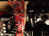
I use 100mm UFL canles with the connector cut off on Dac side. Length is now 90mm and are all same length within 2mm tolerance. The ground is connected on dac side to the shielding of the UFL cables.
See attached picture of the test setup.
Do you think this should work?
I would like to compare this connection to the isolated one.
Though the direct connection can bring noise from ground to the dac, on the other hand the isolator can also introduce jitter.
It would be nice to compare both to see which is best.
Regards,
Thank you for your reply.
I use 100mm UFL canles with the connector cut off on Dac side. Length is now 90mm and are all same length within 2mm tolerance. The ground is connected on dac side to the shielding of the UFL cables.
See attached picture of the test setup.
Do you think this should work?
I would like to compare this connection to the isolated one.
Though the direct connection can bring noise from ground to the dac, on the other hand the isolator can also introduce jitter.
It would be nice to compare both to see which is best.
Regards,
Attachments
OPUS DAC
Make sure the OSF settings on the OPUS DAC are correct for all sample rates. If you have it set to 8x OSF it will only work for 44.1/48. You need to manually change the OSF to 4x for 88.2/96 and 2x for 176.4/192, or you can set it to 2X for all sample rates.
Hi Supersurfer, your comment is very interesting to me cause I've a problem similar to yours.
My WaveIO feeds a TP Opus through uFL. Starting from an indefinite moment a couple of weeks ago (and not related to any circuit change or setting I can remember) I got some very audible distortion, particularly in one channel, but only at multiple of 44.1 and 48, these two sampling rates seem to work correctly.
I tried to swap the dac with a spare board, but nothing, same result.
It's becoming very annoying, cause I've not been successful at isolating the problem.
Make sure the OSF settings on the OPUS DAC are correct for all sample rates. If you have it set to 8x OSF it will only work for 44.1/48. You need to manually change the OSF to 4x for 88.2/96 and 2x for 176.4/192, or you can set it to 2X for all sample rates.
Connections seems to be okay still I was afraid you will use 100mm coax cables 😱 I know because 50mm are often too short for a DIYer to feel comfortable with. Anyway, let's do some 'stupid' choices and please do try to connect those shields from coax cables on both your DDDAC and WaveIO as well (if you didn't do it by now). Even if I fully agree to keep the shields connected at one side of the cable and left it "float" at the other end, it might be possible for it to not function properly in your setup thus I would agree with the idea to build as many ground interconnects as possible, despite the fact it will create gnd loops.
So, this is what I would do:
1. please do keep the coax cables at a reasonable distance one from another. Do not keep them together as are now because if the shields are not working properly then there are high chances of crosstalk between the I2S wires.
2. if this is not working then add gnd connections on both sides of the coax connections. From what I can see, the WaveIO's side is okay because the shields are wired to WaveIO GND by means of the U.FL. connectors. You have to work on the DDDAC side now.
3. Please do try to use only one rack from your DDDAC. From Doede's schematic I can see that the L/R and bit clock are heavily loaded so I'm pretty sure that XMOS is not capable to handle so many loads on those lines... hence my suggestion for testing purpose, to make its life 'easier' by disconnect other racks and leave only one.
The other paths would require a buffer but this will complicate things...
Hi Lucian,
Disconnecting three dac boards will impair sound quality and therefore going that route is not prefeable.
The ground is connected from both sides to the ufl cables so I expect that will be ok.
I find your remark regarding cross talk between the cables a bit strange: these cables are intended for use in enviroments with air pollution like mobile phones and also if you look at the connector used for the isolated output, that uses a completely unshielded cable. I also have experience with using like 30cm length of I2S cables between a philips CD pro loader and a dac with good results.
But maybe you are right that the xmos is just not stong enough to drive the load. That will also make it possebly more prone to distortion from radiation. Is there a simple way to amplify the signal?
Make sure the OSF settings on the OPUS DAC are correct for all sample rates. If you have it set to 8x OSF it will only work for 44.1/48. You need to manually change the OSF to 4x for 88.2/96 and 2x for 176.4/192, or you can set it to 2X for all sample rates.
Hi barrows, thank you for your info. Maybe speaking about opus it's quite ot in this thread (I'm sorry Lucian if that is the case), maybe not. My Opus (8740) card settings are the same since long time (I2S 1, DSD-DEEMPH-MODE 0, IWO 1, DIFFHW 0, FSEL-MUTE-OSR disabled) and the problem emerged only recently. I'm still investigating.
max ufl length?
While waiting for my board I've gotten some 10cm ufl cables, since this would be a much easier installation than anything shorter. I could get it down to 7cm cables if I start to angle the plane of the board and "wedge" it in. Is 10cm too long? Is it a matter of not working at all, or are there also more subtle improvements the shorter the cables get?
Connections seems to be okay still I was afraid you will use 100mm coax cables 😱 I know because 50mm are often too short for a DIYer to feel comfortable with.
While waiting for my board I've gotten some 10cm ufl cables, since this would be a much easier installation than anything shorter. I could get it down to 7cm cables if I start to angle the plane of the board and "wedge" it in. Is 10cm too long? Is it a matter of not working at all, or are there also more subtle improvements the shorter the cables get?
- Home
- Source & Line
- Digital Line Level
- XMOS-based Asynchronous USB to I2S interface