Good to hear about your result, Eldam.
I wanna try with TDA1541(non-A) with the mclk clock from Waveio to pin 4. I think I will need Mclk/2 for the clock.
I hope this weekend I will have time to finish the board.
Hmmm, I missed out Ian's works,lately.... He did many nice things....
I wanna try with TDA1541(non-A) with the mclk clock from Waveio to pin 4. I think I will need Mclk/2 for the clock.
I hope this weekend I will have time to finish the board.
Hmmm, I missed out Ian's works,lately.... He did many nice things....
Last edited:
IIRC the pin 4 of TDA1541 non-A accepts 12 MHz ! (datasheet says that it is only 6 MhZ Fsck on pin 4 with the A datasheet but the double on non-A !)
I had the same idea than you as my understanding is you have better to use the pin 4 then pin 2 in I2S mode with the TDA1541 non A ! (son pin 2 unpluged and floating) ! My understanding is when using the A chip with pin 2, bettere to ground pin 4 but not sure: complicate ! some relation with pin 28 and pin 8 or 6 iirc (yes a simple DEM decoup pins !) as well !
I should say Ifind in normal pin 2 conf the TDA1541 non A to be very good (different beast than the A !) ! Ah I have to verify it's not marked Y (I read somewhere if I 'm not mistaken than some non A marked Y (as prototype... and marketed on some Philips/Marantz) has the cap Inside in the Fdem (between pin 16&17). So with pin 4 it should be even better !
Ah sorry for the off topic.
Last edited:
I might need to do more source on TDA1541.
I thought pin 4 is for system/master clock 12Mhz.
I have to try it. There is no external DEM clock as I know but I think the extra master clock could compensate for that.
I use my moded Revox B225 14 bit, that is already sounds really good for me.
I thought pin 4 is for system/master clock 12Mhz.
I have to try it. There is no external DEM clock as I know but I think the extra master clock could compensate for that.
I use my moded Revox B225 14 bit, that is already sounds really good for me.
Last edited:
I think you're right, All those informations exist here on DIYA and elswhere...
I will try tomorrow my non A in I2S mode with pin 4 as a Bclk instead pin 2 with Ian's Clock II board and 45/49 crystals.
I never tried my TDA1540 chips with the PCM board yet, but I should !
Well, just to say I finded the combo Wave I/O musical in simultaneous mode... so it should work with TDA1540 14 bits as well (but haven't a board with uf-l plugs ! I have the old Marantz Cd 45 or 40... don't remember with cdm2 mechanism !)
Last edited:
Hi Everyone,
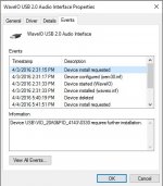
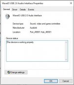
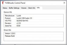
Just got done hooking up a Wave IO to my Opus DAC, I'm using an Otto to switch the I2S between spdif receiver in and the Wave IO. The Otto is switching properly and when I set it to the SPDIC receiver I2S the DAC plays fine, switching over to the Wave IO I2S is silent, she won't sing. The Wave IO is powered by a separate 5 vdc supply the external power jumper J13 is set to ext and a small green on the board is lit. The usb input jumper is set to brd. The Wave IO I2S assignments to the opus that I'm using are BC (wave) to BCK, MC(wave) to MCK, LR(wave) to LRCK, DT(wave) to Din, and I've hooked an isolated gnd from the wave to the gnd on the opus I2S input. I have the isolated I2S V+ connected to the external 5 vdc psu that is hooked up to power the Wave IO board. I am trying to use a laptop with windows 10 as a source using Foobar 2000. Windows seems to recognize the Wavio driver but when I look in device manager it seems that it wants something else installed that wasn't in the setup. I've attached a picture of the message. I know that some of you have successfully used the Wave IO with Opus DACs so would be appreciated.
Thanks,
PJN
Attachments
Hi folks, I've a couple of ancient WaveIO boards in various devices, just ordered a new one to go into a USB to SPDIF convertor. I've done this previously, using the isolated SPDIF output straight to a BNC connection for co-ax connection to the DAC. I'm now looking to add optical output and have the necessary, in this case Sharp, optical output connector. This requires 5V power, and I wonder if it's permissible to take the feed for this from the 5V input into the Wave board? I'm using an external power supply to feed the board.
Hi All,
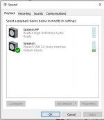
I played around a bit today and managed to get sound out of the Wave IO. I needed to put it on USB power to get my PC to recognize the device reliably, after that I switched the power jumper to ext power. I needed to change my sound output device in windows to the Wave IO to get sound out, but so far things still need some work. the sound from both Foobar 2000 and Pandora streaming is full of crackles, like a beat up old vinyl record. Here are some screen shots. Does anyone have any ideas as to why this thing crackles ? I'll post some pics of my installation.
Thanks
Paul
Attachments

Paul,
You have a few potential issues there but you should start by NOT using WaveIO as the default Windows sound device. This setting sends all system sounds to WaveIO; you don't want that...
Nick
You have a few potential issues there but you should start by NOT using WaveIO as the default Windows sound device. This setting sends all system sounds to WaveIO; you don't want that...
Nick
WaveIO power consumption (External PSU)
Missing for a couple of days due to an unplanned trip outside Romania... I'm sorry about that! I'll get back to an earlier post when I was asked about WaveIO's power consumption in different cases.
@ xcj999: did you thought I forget your request? 😛
Below are few links to screenshots taken with my phone on Agilent DMM (please excuse the quality...). Every link contains details about what kind of track was played when measurements were taken.
So, here we go:
WaveIO in Idle mode
WaveIO playing 352.8 fs tracks
WaveIO playing 384 fs tracks
WaveIO playing Native DSD64 tracks
WaveIO playing Native DSD128 tracks
WaveIO playing Native DSD256 tracks
WaveIO playing DoP64 tracks
WaveIO playing DoP128 tracks
... I hope all above links are correct! Measurements were taken on a range of 100 samples where you can find minimum, average and maximum values. I know too many digits are somehow overkill but I hope it helps!
As for the rest of you, please allow me few more hours to take one request at a time.
Kind regards,
Lucian
P.S. From unknown reasons, all the links excepting the first one does have the "www.diyaudio.com/forums/" text before the valid web address thus breaking it. I don't know if this is a bug or something but if my post will not be as expected, here's a .rar archive with all images posted above.
Edit: it didn't worked and I have no energy left to be mad so there are two choices: first is to manually remove the "www.diyaudio.com/forums/" text from each link or download the whole archive... I prefer the second option and get over it!
Last edited:
Nice work on the board. Am I correct that there is no I2S input available? I am going to be working on a PC based audio project soon and am looking for a good 32/384 capable USB reciever. Would want to hook an ADC up which would be accessible by the PC though.
@ merlin el mago: Never got any email from Thesycon lately regarding your error. 😕 I guess I have to contact Mr. Udo Eberhart when it comes to technical details but since you sent your card here I'll do it after a full HW inspection. I'll keep you posted through PMs!
@ Crom: Regarding +5VUSB and if it still helps, today I'll run few experiments here! I have three different PCs, each one powered by Windows OS and I'll remove the +5V from my test USB cable while powering one of available WaveIO boards from external PSU (made by Doede, liked here) just to see what will happen.
If there's any particular configuration you want me to try out here just let me know!
@ suffolk tony: I don't see the reason why it should not work! It's not like that Sharp optical transmitter is a power hungry beast to look for any additional current reserve for your external PSU (or I'm missing something?) so you might try to power it from the same power source as WaveIO. Anyway, I guess there will be some issues with the output signal's voltage threshold. If you're going to use any of the SPDIF outputs of a WaveIO stock board then keep in mind the voltage swing is around 0.5Vpp, quite useless to drive your optical transmitter thus it will not work with such a small signal.
Obviously, above affirmation will not be valid if I've customized your card(s) prior shipping. I can't remember so many details... 😱
Edit: there's no need to worry about GND isolation so we skip over it in this case!
Kind regards,
L
Last edited:
Thanks from me too Lorien. As I'm using a separate power supply then the voltage won't be an issue.
Ditto, thanks from me too. Definitely still useful. I would just like to know if there is a way to use the waveio without the +5v USB connection in place (but retaining the GND).
Alternatively, if it's possible to turn the +5v off after handshake, that's fine too and would be useful to know - but I can't get this to work either.
I've read posts confirming it is and it isn't possible(!) so just would like confirmation.
Thanks,
Crom
Alternatively, if it's possible to turn the +5v off after handshake, that's fine too and would be useful to know - but I can't get this to work either.
I've read posts confirming it is and it isn't possible(!) so just would like confirmation.
Thanks,
Crom
Paul,
You have a few potential issues there but you should start by NOT using WaveIO as the default Windows sound device. This setting sends all system sounds to WaveIO; you don't want that...
Nick
Hi Everyone,
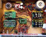
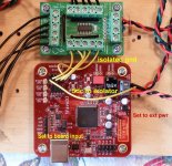
Here are some pics of my install. Please let me know if I've done something wrong hooking things up. I tried several different USB cords, no change with any, still crackling like crazy. I have used these cords on another DAC that uses a ministreamer no issues so I'm supposing they are not the problem.
Nick,
If you could let me know what potential issues I may have I would greatly appreciate it. I'm not a windows or software expert so I'll be happy for any help I can get.
Paul
Attachments
@PJN:
I'm pretty sure I'm no expert either but I'll do my best😱.
1. were you able to get sound from WaveIO without selecting it as the default Windows sound device? I think this is critical.
if not then..
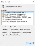
2. your driver installation looks doubtful so you might want to try a re-run of the set up. then go back to 1. Post your result.
Push comes to shove you may need to bypass the Otto to make sure it's not a contributor but let's get this far.
Note that I do not use Opus nor the isolated output from Wave IO so won't comment on your layout😉
N.
I'm pretty sure I'm no expert either but I'll do my best😱.
1. were you able to get sound from WaveIO without selecting it as the default Windows sound device? I think this is critical.
if not then..
2. your driver installation looks doubtful so you might want to try a re-run of the set up. then go back to 1. Post your result.
Push comes to shove you may need to bypass the Otto to make sure it's not a contributor but let's get this far.
Note that I do not use Opus nor the isolated output from Wave IO so won't comment on your layout😉
N.
@ PJN: looking at your pictures (and avoid upsetting anyone) I would say that the main source for your issue is poorly made wring. At least for I2S...
Let me add few reasons to sustain above statement:
1. As I can see, you wired the V+ pin (power supply of the output side of the isolator) to the +5V external PSU of WaveIO. This is NOT recommended since doing so, you will bypass this chip and its main function = to isolate grounds. The related "isolated" ground (which is reference for all i2S signals) is directly wired to Otto. So, since the I2S signals are NOT differential, there has to be a returning path back to WaveIO's main GND (as long as you powered the output side of the isolator with +5Vdc from J13 screw-type connector). Is there such a connection between the, let's say, GND of Otto (which is also GND of the output side of isolator) and main GND of WaveIO? Check this connection with a multimeter!
If so, how long this connection is? I ask because, for speedy I2S signals it really does matter! My assumption is the GND connections is made through power supplies... and if I'm right... this is a reallllly long path...
2. Secondly, I strongly advice you to bypass Otto - but only for testing purposes! After you'll solve your issue you can freely add it to your system!
3. Check if all your I2S wires have the same lengths and are as short as possible!
4. The simplest solution I see now is to bypass Otto and add a +5Vdc (or +3.3Vdc) wire from anywhere else than J13 making sure that main power supply rails of WaveIO (connected at J13) does not have a direct contact to anything else following output side of the isolator!
As for drivers, firstly I want to thank to Nick for his support but I would suggest you to try first at least one of above HW changes before reinstalling drivers!
Please keep me posted,
L
Last edited:
any other man, and i would have had doubts 😉
thanks for all these measurements!

- Home
- Source & Line
- Digital Line Level
- XMOS-based Asynchronous USB to I2S interface