I'd like to build this amp as all my 'DIY' power amps so far have been class D and that's just basically wiring in a PSU!
I shall have some boards made from JLPCB. Is 2oz critical or can I go for 1 oz copper? Makes a big difference in cost.
I've found those nice Dell sinks here for £6 each and RS has stock of the chips. I have a gain clone psu here and I think i have a trafo.
The rest of the Mouser BOM is very reasonably priced isn't it!
If he used them on both sides of the chip the shoulder on the back side would prevent the cip from laying flush against the insulator or am I missing something here?
Sorry, that was a very late post. Forgot to refresh the page first!
No problem. I should have been clearer in the first place.
Cheers
The BOM is not expensive/ I would like to give you a price but I always order more stuff than is needed. The board is set up for Molex mini-fit jr connectors for power in and speaker out so you will need to order the mating plugs and pins for those plugs, I was able to steal them off old computer power supplies. The input connector is a Molex kk and you will need the mate and pins for that also. Lastly 18 ga magnet wire for the inductor.
As I have learned you will need to insulate the TAD7293 from the heat sink with a pad and shoulder washers.
I think that is everything.
As I have learned you will need to insulate the TAD7293 from the heat sink with a pad and shoulder washers.
I think that is everything.
The board is set up for Molex mini-fit jr connectors for power in and speaker out so you will need to order the mating plugs and pins for those plugs, I was able to steal them off old computer power supplies.
That is a brilliant idea! I have a box of old computer PSs... That saves some $.
Also, remember that the Excel sheet BOM lists parts for one board so you'll have to double everything...
Cheers
Another good idea is an eight pin socket for U4.
both boards are working with the servo operating. The problem was no connection between left leg of C25 and pin 4 of U4. So no negative rail to the servo. Offset was -4.5V and it dropped to 6.1mv with a jumper from C25 to pin 4 of U4.
I must have burned the trace while stuffing the board as the offset was -4.5V from the first power up with the variac. The amps sound very good but it is hard to say more as I am using a little oval speaker as a test speaker.
Hi X,
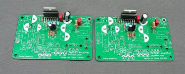
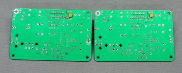
Boards arrived today. Thanks to you, Dibya, and Jhofland for your contributions. Time for more soldering.
MM
Boards arrived today. Thanks to you, Dibya, and Jhofland for your contributions. Time for more soldering.
MM
both boards are working with the servo operating. The problem was no connection between left leg of C25 and pin 4 of U4. So no negative rail to the servo. Offset was -4.5V and it dropped to 6.1mv with a jumper from C25 to pin 4 of U4...
Glad you found the problem!
The storm delayed boards finally arrived just in time for another winter storm. Now the fun begins. Thanks X, Dibya and Jhofland. Will incorporate 680pF @ C10 and 10pF across R1 as standard build.
You probably should add MOLEX#s 0039012060 (6 position housing), 0039012040 (4 position housing) and either 0039000039 (24-18AWG crimp female pins) or 0457503112 (16AWG crimp female pins) to the BOM if you don’t have old computer PSs to steal them from. ;>)
Numbers correct?
Pete
You probably should add MOLEX#s 0039012060 (6 position housing), 0039012040 (4 position housing) and either 0039000039 (24-18AWG crimp female pins) or 0457503112 (16AWG crimp female pins) to the BOM if you don’t have old computer PSs to steal them from. ;>)
Numbers correct?
Pete
I have a set of these boards available with some parts loaded. I had configured them to drive my headphones but it didn't work out as I'd hoped.
Parts I used specific to my needs were removed with professional desoldering equipment (Pace), and the flux cleaned off with IPA. The 7293's were sourced from a USA distributor. A 10pF NP0 cap is added across R1, and two 680pF mica caps are included for C10. Can ship immediately. Contact me by PM.
Edit: I have XRK's blessing to offer these here.
Attachments
Up and running on tabletop ...Single Antek 3220, 24000uF per rail, sounds fine on test speakers. Had to detach the incoming signal ground (from J2, pin 2) and connect to the PS ground because of a feedback loop.
DC offset at 13 & 15 mV. Would have thought 4-5 mV would have been measured.
Cheers
DC offset at 13 & 15 mV. Would have thought 4-5 mV would have been measured.
Cheers
Good to hear you got it up and running Turion. Interesting apprach with the RCA ground to PSU star? 15mV is still within reasonable limit for speakers - but that is odd that it is not closer to 5mV. You can try changing R15 to 10k and that is still a safe value according to Jhofand. That will give you some more gain on the feedback loop to zero it out.
Thanks X...
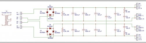
I’ll try that today. Here the schematic of the PS I’m using with tranny being the Antek 3220, C1-4 are 12000uF caps. GNDs are marked at outputs, so yes a sort of PS star.
I’ll try that today. Here the schematic of the PS I’m using with tranny being the Antek 3220, C1-4 are 12000uF caps. GNDs are marked at outputs, so yes a sort of PS star.
Attachments
Hi Pete,
Can you post pics of your setup showing how your psu and amp boards are wired? Strange that you had to move the signal gnd to the psu?
Can you post pics of your setup showing how your psu and amp boards are wired? Strange that you had to move the signal gnd to the psu?
I’ll take some pics after breakfast..😉
I had a similar ground loop problem with my My_Ref Fremen LM3886 amps (onboard PS to each amp board) except I grounded those boards to a GLB through the board’s PGND connection and the incoming signal GND was not diverted from its normal connection path. Those boards have a "floating ground."
I don’t have any issues with any of the TPA3255-base class D amps but I did with IRS2092 class D amp I put together. Just something in my system I guess.
Ok, thanks.
These boards have built-in ground loop breakers connected to the mounting pad with the copper pour around it. Make sure that that pad is connected to your star ground. You should not have to remove the signal ground from that board, because it is protected by it’s on-board ground loop breaker.
These boards have built-in ground loop breakers connected to the mounting pad with the copper pour around it. Make sure that that pad is connected to your star ground. You should not have to remove the signal ground from that board, because it is protected by it’s on-board ground loop breaker.
As I remember, but I’ll check that again, I did have each board connected to the earth star ground through those special corner pads. It didn’t help with the issue. Everything is on a wood surface at this point so normal "assembled in a case" grounding issues haven’t reared their ugly head yet.
- Home
- Amplifiers
- Chip Amps
- Xmas Amp - Dibya's TDA7293 by Jhofland