A Rat Rod should be perfect for vertigo, they are usually really, really low. Not enough rust action happenin' on that jeep! She's a beaut!fwiw I could feel the air from the aperture on this K18 10 feet away at high levels and very little cone movement

I like most kinds of hot rods - need a mechanic to help me fix one once nice rotting in my driveway ;^(
its built on a postal jeep -
I've had chronic vertigo for decades - then heart probs

I'm sure after a few years of being under UV rotted tarps, wet ground, high humidity and cats tracking mud on every square inch of everything, that there's some beautiful rust happening 😀
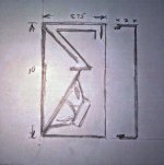
The inside view pic shows duct opening at top rear and the messy area in the middle is where the foam core is caulked to the rear edge of the shelf. It extended too far to miter it to the shelf and I was too anxious to hear it to ponder a solution. I may add a bit of foam core to the rear of the rear of the shelf for number 2. I took the choke strip off the rear panel so I don't think a thickness of foam core there will hurt anything, after all it's a kluge at best.
In the side by side pic the one with the mod is on the left. You can see through the vent to the rear panel in the other one. They are approx 10" tall.
Beauties by no means but will reside in my garage to be heard rather than seen.
I missed this post somehow. Anyhow nice work!
Yes, I started with your suggested size for a double and using your akabak script, played with the dimensions. Akabak suggested best tuning at 300mm, but I guessed on shortening duct to 265mm to take into account right angle bend and end effects.
At the moment, just lined but haven't stuffed the top of the rear chamber yet. The bass is really good - I don't have any equipment but a tone generator gave good response down to 45Hz, so they do seem to tune lower than akabak suggests.
It is a bit late to play them loud so will post more when I have played with stuffing, but I like them and will build up a pair in plywood. They certainly move a lot of air - you can feel the wind at the top of the aperture.
We look forward to seeing more detailed plans and listening impressions. The PA130-8 is kind of an under rated driver - they sound very natural and dynamic. In parallel you are probably getting 95dB at 2.83v!
those beauties made of foam or light plywood could be yoked together and powered with TPA3116 for a powerful boombox
I have decided to extend the rear of the boxes by 3" using some 3/8" ply scrap from the same era as the original build, then use foamcore to extend the duct already built and add a duct to the other box. The dimensions on the sketch for the addition should be 3" and the duct will not turn down at the rear as shown. I will use some laminate flooring felt underlay to line the rear panel. No calcs or testing, just a seat of the pants approach to hopefully get some bass extension.
Attachments
Last edited:
Now I have some time to carry on with this design, I have been tinkering to get the dimensions right before I cut the plywood. The effective length of the duct seems to be significantly longer than the actual figure I am using in Akabak, causing the speaker to tune deeper but with a noticeable dip in the 50s Hz, with a rise down to about 45 Hz. Currently, my foamboard prototype has a length of 25 cm and a right angle bend. I guessed adding on twice the duct height to take into account the right angle and the end effects, but I think the end effect is significantly more, especially as the ends are baffled. There is an interesting solution at this link for a rectangular section organ pipe - the end effect works out 0.3 * height + 0.8 * sqrt(area). In my case with a 2.8 cm * 20.3 cm duct, this works out at 6.87 cm, suggesting my duct is much too long!
End correction at flue pipe mouth
End correction at flue pipe mouth
That correction seems excessive. The wrap around ducts I have designed for bandpass subs have been pretty accurate with Akabak. It's MLTL's where there seems to be more correction needed. Sometimes a factor of 2 off if not using any correction at all. The Akabak manual discusses how to apply corrections. Since XKi is more like a bandpass sub, I am thinking it is closer to actual length needed. Maybe 15% off at most. Make the duct in such a way that you can access it through driver cutout and drill extra Swiss cheese holes to tune to exact frequency.
I have decided to extend the rear of the boxes by 3" using some 3/8" ply scrap from the same era as the original build, then use foamcore to extend the duct already built and add a duct to the other box. The dimensions on the sketch for the addition should be 3" and the duct will not turn down at the rear as shown. I will use some laminate flooring felt underlay to line the rear panel. No calcs or testing, just a seat of the pants approach to hopefully get some bass extension.
Did you ever make this?
Not yet, things keep getting in my way.Did you ever make this?
That correction seems excessive. The wrap around ducts I have designed for bandpass subs have been pretty accurate with Akabak. It's MLTL's where there seems to be more correction needed. Sometimes a factor of 2 off if not using any correction at all. The Akabak manual discusses how to apply corrections. Since XKi is more like a bandpass sub, I am thinking it is closer to actual length needed. Maybe 15% off at most. Make the duct in such a way that you can access it through driver cutout and drill extra Swiss cheese holes to tune to exact frequency.
There is a lot of bedtime reading in the manual. A quick perusal, and have found some information for simple end correction, and also correction for a right angle bend.
For a non-baffled pipe a figure I found is 0.34 * sqrt(area).
In my case with duct of 280 mm length and cross section of 203 mm * 28 mm, the correction is 25.6 mm at each end. Slightly higher than 15%, but in the right ballpark.
Good thing I was close with the 15% 🙂 I need to read the manual more for the end corrections. Which pages or chapter is that on?
I have found several different figures ranging from 0.3D to 0.6D for a circular duct. The manual specifies 0.306D for a free end and 0.425D terminating in a baffle. I can't find it right now but I found a formula to calculate effective diameter for rectangular duct. Will dig up tomorrow.
In the akabak pdf I have, the end correction is mentioned on p.181. There is also mention on p.72, 160, 175 in relation to Helmholtz resonance. The manual also mentions correcting for a right angle bend on p. 161 by inserting an acoustic mass.
In the akabak pdf I have, the end correction is mentioned on p.181. There is also mention on p.72, 160, 175 in relation to Helmholtz resonance. The manual also mentions correcting for a right angle bend on p. 161 by inserting an acoustic mass.
I have been correcting for corners with 3x acoustic mass relative to no corner as recommended by the manual. Thanks for the page numbers on end correction.
Yes, for Helmholtz resonance in a tube, the formula is based on the hydraulic diameter, Dh.
Dh = 4A/P
where A = cross sectional area and P = wetted perimeter.
So for rectangular duct, Dh = 2ab/(a+b)
In my case, duct = 203 mm * 28 mm, giving Dh = 49 mm
End correction for both ends = 2 * 0.3 * 49 = 29 mm
This is within your range of 10 to 15 % of duct length (280 mm).
Now I can relax.
Dh = 4A/P
where A = cross sectional area and P = wetted perimeter.
So for rectangular duct, Dh = 2ab/(a+b)
In my case, duct = 203 mm * 28 mm, giving Dh = 49 mm
End correction for both ends = 2 * 0.3 * 49 = 29 mm
This is within your range of 10 to 15 % of duct length (280 mm).
Now I can relax.
Sorry for double post.
Including the duct corner in the Akabak script, I cut the duct into 2 lengths and add an Acoumass element between them.
The manual states to calculate the acoustic mass as 1.85/(duct height in metres). For a 28 mm duct, this gives me 66 Kg/m4, which completely mucks up the simulation.
However, the manual also defines acoustic mass as (mass of volume) / (cross sectional area)^2
For a right angle bend in a rectangular duct, this works out as (air density) / (duct width) and gives me a much lower value of 6.03 Kg/m3. This doesn't muck the simulation up and in fact gives a result closer to what I am hearing with bass down to 45 Hz.
An externally hosted image should be here but it was not working when we last tested it.
I recall the example in the manual with the dual driver sub woofer as using acoustic mass of 3 for every 90 deg turn. Acoustic mass = 1 for straight duct. Or did I imagine that?
I can't find a dual driver sub referred to in the material I have. I started using the example on p.161 to alter the script for a 90 degree bend in the duct (I used 0.028 instead of 0.05 for duct height).
This made large changes to the output, so dug a bit deeper into the manual.
As I understand, a bend is modelled by splitting the duct into 2 sections, and an acoustic mass is added to where the faces of the duct sections meet. Calculating the acoustic mass is where I have trouble. I don't understand properly what it is - seems to be some kind of inertial quality that reduces change in volume velocity analogous to the effect of inductance on change in current. Based on the Ma=M/(SD)^2 at the start of the section, the simplified calculation given for a right angle bend seems wrong - height is wrongly used instead of width. Maybe I have made a mistake?
Code:
Duct 'Du1' Node=5=6 WD=20cm HD=5cm Len=30cm
AcouMass 'Ma1' Node=6=7 Ma={ 1.85/0.05 }
Duct 'Du1' Node=7=8 WD=20cm HD=5cm Len=30cmAs I understand, a bend is modelled by splitting the duct into 2 sections, and an acoustic mass is added to where the faces of the duct sections meet. Calculating the acoustic mass is where I have trouble. I don't understand properly what it is - seems to be some kind of inertial quality that reduces change in volume velocity analogous to the effect of inductance on change in current. Based on the Ma=M/(SD)^2 at the start of the section, the simplified calculation given for a right angle bend seems wrong - height is wrongly used instead of width. Maybe I have made a mistake?
Yes, I think there is an error in the manual. In the paper linked below, a duct bend is simulated by adding an acoustic mass. The acoustic mass is calculated as 1.85 divided by duct width (width is perpendicular to the plane of the bend). In my case, width is 0.203m, giving acoustic mass = 9.11.
http://www.randteam.de/_Docs/Pub/aes_Euphonia_e.pdf
http://www.randteam.de/_Docs/Pub/aes_Euphonia_e.pdf
You only have one bend - I would not get too caught up in getting the sim of a 90 deg turn exactly as there are plenty of other factors. I have modeled horns with labyrinth turns a total of 12 180deg hairpin turns with the simple acoustic mass 3x for ea turn and the measurements match prediction well. There is also the stuffing losses you have to account for.
- Home
- Loudspeakers
- Full Range
- XKi - X's ab initio Karlson 6th Order Bandpass