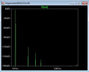
Generg: Increase the input capacitors to 1000uF and the THD plots will be much better. Capacitors that haven't stabilized cause the downward ramp in the "noise floor".
Hello generg,
.OPTIONS plotwinsize=0 does the trick!
(The other options you have posted have little effect.)
When I add only that option and leave the rest of the file as it is (with 1000µF input capacitors) I get this picture:
.OPTIONS plotwinsize=0 does the trick!
(The other options you have posted have little effect.)
When I add only that option and leave the rest of the file as it is (with 1000µF input capacitors) I get this picture:
Attachments
I hope this is no problem ….
Pass Labs X600.8 600 Watt Monoblock Power Amplifier Review - HomeTheaterHiFi.com
in this case this can be deleted or I delete it.
Pass Labs X600.8 600 Watt Monoblock Power Amplifier Review - HomeTheaterHiFi.com
in this case this can be deleted or I delete it.
Hello generg,
.OPTIONS plotwinsize=0 does the trick!
(The other options you have posted have little effect.)
When I add only that option and leave the rest of the file as it is (with 1000µF input capacitors) I get this picture:
ha, ha nothing than good luck….
I do not know what plotwinsize means….. 🙂
is the distortion now like you wanted…?
Yes, the result looks reasonable.
A look into LT-Spice help clarifies the problem:
1. plotwinsize = Number of data points to compress in one window. Set to zero to disable compression.
2. LTspice compresses the raw data files as they are generated. A compressed file can be 50 times smaller than the un-compressed one. This is a lossy compression. This pane of the control panel allows you to control how lossy the compression runs.
=> set allways plotwinsize=0
But the result of post #157 stays the same when I insert that option there too. That is a strong indication that there is something wrong with the MOSFET models. Or these MOSFETs are in fact so (massively) different that they do not act as a differential stage.
Last edited:
and pr many thanks for your .pdf about harmonics, great information and it got a place in the folder "useful texts" in my big "Bastel" folder….. 🙂
There is a review of the X600.8 in hometheaterhifi.com. Pass Labs X600.8 600 Watt Monoblock Power Amplifier Review - HomeTheaterHiFi.com
I find the distortion plots hard to believe, both because of the high levels of H2 (2nd harmonic) and the low levels of H3. Does anyone else share my opinion?
I find the distortion plots hard to believe, both because of the high levels of H2 (2nd harmonic) and the low levels of H3. Does anyone else share my opinion?
The second harmonic dominates the distortion, as intended. We can null it out,
leaving the higher orders, but we choose not to.
😎
leaving the higher orders, but we choose not to.
😎
The second harmonic dominates the distortion, as intended. We can null it out,
leaving the higher orders, but we choose not to.
😎
What how much feedback is needed for that level of H2/H3? I cannot achieve anything close to that with only 10dB of feedback.
From where did you get this 10dB-specification for feedback in .8-series?
I only know this for Xs-amps.
I only know this for Xs-amps.
That's a standard value in most power amps.
10db are rather unlikely: in pics of 6moons review for XA30.8 there can be seen a jumper-selectable gain between 30db and 26dB.
In case of 30dB there would remain a feedback factor of only 6dB, rather close to an open loop design.....
10db are rather unlikely: in pics of 6moons review for XA30.8 there can be seen a jumper-selectable gain between 30db and 26dB.
In case of 30dB there would remain a feedback factor of only 6dB, rather close to an open loop design.....
That's a standard value in most power amps.
I would say that it's common but not standard. In any case, just like issues
with bias and relative harmonic content and all the other stuff, each model
of our amplifiers tends to be a little different from the others - we tweak
the values individually. To make life easy, our input gain modules have
standard components, and various resistor values on the mother-boards give
the unique settings (Currently the only capacitors in the circuits are filters
in parallel with reference constant voltage sources).
And it's true that as you raise the gain from 20 to 26 to 30 dB, you are
reducing the feedback by those proportions.
😎
Pa sez:
....... each model
of our amplifiers tends to be a little different from the others - we tweak
the values individually.....😎
From where did you get this 10dB-specification for feedback in .8-series?
I only know this for Xs-amps.
My initial estimate of the feedback values was based on damping factor, the number and types of the output fets, and the output fet degeneration resistances. For the XA30.8 this gave me something close to 10dB. OTOH, since my estimate was based on datasheet transconductance information and default Spice VDMOS values for IRFP240 and IRFP9240 FETs, my feedback estimate is probably too low. I found that the actual measured transconductances at 300mA are about 1/2 of those predicted by the default Spice models, thus requiring more feedback to obtain the specified damping factor. If someone have a better estimate I would like to know. Of course, one could adjust the feedback to obtain the desired h2/h3 spectra.
A prototype..
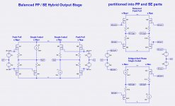
Hello everyone. The schematics in the image are by lhquam from his post#119. The Bridged Anti-Phase Single Ended [BAPSE] schematic was reduced to a practical prototype so as to understand/characterize its operation; because of its central importance to the bigger amp.
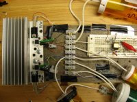
The middle photo shows this prototype. The output stage of BAPSE is on the heat sink. It uses complementary bjts [instead of Mosfets], and LM337 plus LM317 voltage regulators operating as their CCSs with each idling at 0.3A.
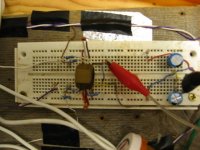
The right photo focuses on the generator of the required balanced signals, and current drivers to BAPSE which is based on NE5532 Op Amp [original Signetics] It is underneath the pipe fitting which is its heat sink [bonded with cyano acrylate]; because this Op Amp normally runs a bit warm.
I'll show schematics and characteristic performance. I've listened to it already. Sounds great.
Hello everyone. The schematics in the image are by lhquam from his post#119. The Bridged Anti-Phase Single Ended [BAPSE] schematic was reduced to a practical prototype so as to understand/characterize its operation; because of its central importance to the bigger amp.
The middle photo shows this prototype. The output stage of BAPSE is on the heat sink. It uses complementary bjts [instead of Mosfets], and LM337 plus LM317 voltage regulators operating as their CCSs with each idling at 0.3A.
The right photo focuses on the generator of the required balanced signals, and current drivers to BAPSE which is based on NE5532 Op Amp [original Signetics] It is underneath the pipe fitting which is its heat sink [bonded with cyano acrylate]; because this Op Amp normally runs a bit warm.
I'll show schematics and characteristic performance. I've listened to it already. Sounds great.
Attachments
I reran the damping factor calculations for my LTSpice simulation of a XA30.8-Guess using Bob Cordell's subthreshold VDMOS Spice models for the IRFP240 and IRFP9240 FETs http://www.diyaudio.com/forums/soft...-power-mosfet-models-ltspice.html#post4158594. With only 10dB of feedback I got a damping factor of 59 rather than the 150 on the Pass Labs spec sheet. Thus I need about 18dB feedback in my circuit to get to a damping factor of 150. My bench measurements of those FETs at 300mA agrees fairly well with the new Spice models.From where did you get this 10dB-specification for feedback in .8-series?
I only know this for Xs-amps.
Going through my old notes, the OL gain of the front end is in the high 30's
of dB, and since the output stage is a follower, you can expect something
like 18 dB of loop feedback if the amplifier gain is is set at 20 dB, and
something like 8 dB if the gain is set at 30 dB.
This varies by model - the front end is loaded by resistance as well, and
this can vary by model. Also there are examples where we have introduced
a proprietary local feedback which runs the front end at lower open loop gain.
😎
- Status
- Not open for further replies.
- Home
- Amplifiers
- Pass Labs
- XA.8 single-ended current sources