One thing I found out last night is that lhquam's idea from post
http://www.diyaudio.com/forums/pass-labs/264094-xa-8-single-ended-current-sources-6.html#post4111512
can not only be used for setting a constant current but also it can be used as means to control the gain of the buffer stage. I only played around with 2 of the resistor values but the results are very promissing. And with these resistor it is not necessary anymore to delete any MOSFET. Rlnc=1k and Rlnv =1m are the usual values in an amplifier, means outputstage is tightly coupled to the driver stage and not to the output of the amplifier.
Attachments

all roads are leading to Rome
though , all one needs is to - choose one , then go all the way through it

though , all one needs is to - choose one , then go all the way through it
That is a problem for me and maybe somebody has got a solution: Sometimes it is very difficult for me to get the Spice modells running. It takes hours. Afterwards I have no plan which files I changed to get it running. Because nobody else complained about these problems before, I thought I just didn't get it right. Solution would be, if sombody has got a (sturdy) workflow that describes how to create a stand alone version of the simulation files. The simulation modells I use are the common files that are freely available in the internet. Those without a copyright mark I put in the appended file.For the others please use internet search.
That zip file of model defs did the trick. I can now run your sims. I need to reciprocate with my amplifier simulation, which is somewhat more complicated and has many more variations.
BTW: I have a variation of the irfp240kst and irfp9240kst models that are parametrized by the number paralleled fets you want to simulate. This makes it easy do perform simulations with arbitrary numbers fets in the 4 quadrants of the balanced amplifier (including fractional number of fets). I will show you how to use them in a output-stage simulation.
I also have some different simple constant current sources in attached .asc file.
Attachments
Last edited:
pr: Here is a zip file containing my experiments for the output-stage, parametrized by the number of fets in each quadrant. You will find that the parameter values and simulation is controlled from a script file, which is mostly commented out. When you are able to comprehend this script file you are well on your way to being a SPICE Master. I hope it is useful to you.
Attachments
When you are able to comprehend this script file you are well on your way to being a SPICE Master.
I always wanted to be a SPICE master, so cheers for that.
😎
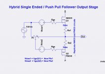
Hello lhquam and pr. I hope that I am not coming at you from left field with this post. My purpose is to bring to your attention that a "STASIS" or a constant current constant voltage [CCCV for short] output stage has an intrinsic property of high loudspeaker damping and/or low output impedance which is readily attained without overall feedback. An image of a simple and simplified LTSpice model of a balanced CCCV is shown. I humbly suggest that you consider its temporary substitution in your models for the diyF4 power output stages..
I also show LTspice .asc files for the Balanced Symmetric CCCV [of image], and for the two possible Balanced Asymmetric CCCVs which are the principal subject matter.
I hope that the following observations from LTspice spark a heightened interest in pursuing the proposed:
1. BalSymCCCV has very low distortion and is devoid of k2. It is or has the sole role of a control or a reference model.
2. The two BalAsymCCCVs have higher %THD than BalSymCCCV, They are, and/or introduce a rich source of k2 [the beef!]. Their %THD are different in magnitude because the articulation of their asymmetry is different. Both models are the DUTs
This proposed approach will allow you to untangle [and thus further understand] the effects of the important variables of damping, overall feedback [or lack thereof], the nature of the FE etc
N.B. Mr Pass wrote a comment in the back flap of a recent article in Linear Audio for its author who discussed distortion in amps operating open loop. The proposed may jive/fit into this.
Best regards.
Attachments
all roads are leading to Rome
though , all one needs is to - choose one , then go all the way through it
This was only true from 8. century B.C to the 7th A.D…..
today all roads go to a small town Bac behind the Iron Curtain……
😀😀

btw.
I always wanted to be both Spice and AP Master ........ but damn short circuit between headphones is hard to fix

you are court master of the Pass Labs Forum, that is a big job and needs much brain….
sorry for the many compliments I will stop immediately!
sorry for the many compliments I will stop immediately!
Nice programming example, very enlightening!pr: Here is a zip file containing my experiments for the output-stage, parametrized by the number of fets in each quadrant. You will find that the parameter values and simulation is controlled from a script file, which is mostly commented out. When you are able to comprehend this script file you are well on your way to being a SPICE Master. I hope it is useful to you.
What I am still searching for is a (sturdy) workflow that describes how to create a stand alone version of the simulation files. In other words:
An instruction "manual" that describes
- which files need to be prepared (.asc, .asy, .sp3 and so on) and
- how they need to be prepared (edit path names for example) so that we get a stand alone version. This stand alone version
- contains an instruction list (if necessary) that shows how to get the stand alone version running (something like <copy files xyz into path "c:\Program Files (x86)\LTC\LTspiceIV\lib\sub"> ).
In the past I had to make a lot of changes to files to get the simulation running, like copying files to LTSpice directories, renaming path names, search for parameter files, link it into the project - until finally LTSpice performed the simulation.
The instruction "manual" would make it easier to share simulation files, for those who create them and for those who download them.
Here is a 1st order set of instructions for standalone simulations:
- Your simulation should not depend on any modifications you might have made to the LTSpice libraries.
- Copy your simulation files to a fresh directory which contains everything other than the LTSpice libraries. You need the following:
- .asc, .sub, .lib files
- .asm files must be in the same directory as the .asc file(s)
- Make sure all .include and .library statements refer only the directory containing the .asc file, i.e. the pathnames do not have any directory specification.
Nice programming example, very enlightening!
What I am still searching for is a (sturdy) workflow that describes how to create a stand alone version of the simulation files. In other words:
An instruction "manual" that describes
- which files need to be prepared (.asc, .asy, .sp3 and so on) and
- how they need to be prepared (edit path names for example) so that we get a stand alone version. This stand alone version
- contains an instruction list (if necessary) that shows how to get the stand alone version running (something like <copy files xyz into path "c:\Program Files (x86)\LTC\LTspiceIV\lib\sub"> ).
In the past I had to make a lot of changes to files to get the simulation running, like copying files to LTSpice directories, renaming path names, search for parameter files, link it into the project - until finally LTSpice performed the simulation.
The instruction "manual" would make it easier to share simulation files, for those who create them and for those who download them.
It is probably more complicated than you think.
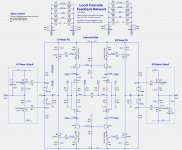
When I look at the "simplified" conceptual schematic I have 4 complementary
Jfet input devices, 4 complementary bipolar cascodes, 4 complementary
voltage gain Mosfets and 4 complementary Mosfet output followers (in real
life as many as 80 followers) and these are just the actual signal path devices,
not counting current sources and voltage references.
There are potentially 37 resistors that affect the gain and feedback (not
counting output Source resistance, input resistors and Gate stoppers), 8 are
degenerative, 8 are Drain loading, 4 are main loops, 1 is both loop and
degeneration and 16 are cascode feedback.
This allows a lot of tweaking, best done over a long period of time, listening
with one eye on the scope.
😎
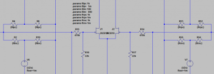
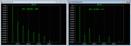
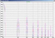
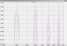
Something like this? The resistor values haven't yet been rounded to standard 1% values. The harmonic plots are at 1W, 4W, 16W, 30W and 60W.
Attachments
I tested the damping factor of the above circuit by measuring output with 1R and 16R load resistances between Out+ and Out-. The cascode feedback shown above causes the output voltage to increase as the load resistance is decreased which implies a negative damping factor! Very weird. 😕
........weird........
(without judging did you got exact Papa's cascode feedback arrangement or not ,which I really don't know) that one is just one of Papa's middle names
(without judging did you got exact Papa's cascode feedback arrangement or not ,which I really don't know) that one is just one of Papa's middle names
I inferred this arrangement based on my own experiments (simulations) which originally used only the front-end outputs in the cascode feedback, and based on Papa's recent post #292 http://www.diyaudio.com/forums/pass...gle-ended-current-sources-30.html#post4274821 describing resistor counts of different types. When looking at the K3 phases of different linear combinations of final outputs and front-end outputs I noticed the combinations that could cancel K3 when used in cascode feedback.
Actually, I left some resistors out. There's a few more.
Because it's a balanced circuit you can play with feedback at all three pins of
each of the cascodes, (assuming that you isolate the Bases from each other)
and there are cases where it is better to cap couple the feedback for DC
stability when the feedback tends toward positive.
😎
Because it's a balanced circuit you can play with feedback at all three pins of
each of the cascodes, (assuming that you isolate the Bases from each other)
and there are cases where it is better to cap couple the feedback for DC
stability when the feedback tends toward positive.
😎
😱 More resistors! More options!
Yes, inserting feedback from Out+ to the bases of the +Phase cascode transistors might work better than inserting Out- into the emitters. I rejected the idea of inserting the feedback into the cascode collectors because it would change (lower) the impedance of the drain loading of the JFETs. Also the PSRR seems to be better with the emitter feedback, since the voltage dividers for the feedback circuit and the cascode base reference voltage are balanced.
What about the negative damping factor of -60milliOhms that I encountered? Have you seen that in any of your testing? I am not sure that it is a problem.
Last edited:
Injecting at the Drain presumes regulated or well-filtered front end rails.
In the latter, that's where you think of maybe having a cap in series on the
feedback for DC stability. This being also true when the feedback is positive
in either case.
I would have to see what your connection is to comment on the negative
impedance. At such a low value, it's not likely to be a problem, but it might
be an interesting sound.
Also don't assume that because I have identified a possible feedback
situation that I have tried it - there are simply too many to run through all
the permutations.
😎
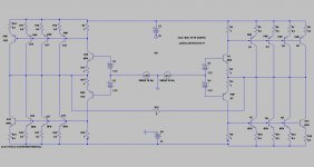
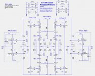
Please find attached a simplified schematic which maybe useful in lhquam's recent LTspice amp. It uses asymmetric diyF5 output stages, and keeps his desired FE. Its attached .asc file does not run as written.
Best regards.
.
Best regards.
.
Attachments

Injecting at the Drain presumes regulated or well-filtered front end rails.
In the latter, that's where you think of maybe having a cap in series on the
feedback for DC stability. This being also true when the feedback is positive
in either case.
I would have to see what your connection is to comment on the negative
impedance. At such a low value, it's not likely to be a problem, but it might
be an interesting sound.
Also don't assume that because I have identified a possible feedback
situation that I have tried it - there are simply too many to run through all
the permutations.
😎
I figured out the conditions for a negative damping-factor. The local feedback circuit is essentially Hawksford Error Correction modfied to use FE-Out- into a resistor summing junction rather than FE-Out+ into a difference circuit (transistor base). There is a parameter which determines the resistor sizes and thus the amount of feedback. When the parameter is increased past the approximately the K2 minimum, the damping factor goes negative. A simplified circuit diagram is shown.I would have to see what your connection is to comment on the negative
impedance. At such a low value, it's not likely to be a problem, but it might
be an interesting sound.
Attachments
- Status
- Not open for further replies.
- Home
- Amplifiers
- Pass Labs
- XA.8 single-ended current sources