Hello pr. The Right power output stage in the schematic "Aleph..Mit geggen.." shows eight P mosfets, and eight N mosfets. Should the number of P mosfets in it be seven instead of eight so as to match the seven N mosfets of the L power output stage in order to inject asymmetry? Flip side, is this intentional which itself is also asymmetry.
Edit. This is an elaborate schematic which points to your ability of "great mastery" of LT simulations, and knowledge of amplifier electronics.
Found the negative feedback nodes noted by lhquam after I magnified the front end circuit.
Edit. This is an elaborate schematic which points to your ability of "great mastery" of LT simulations, and knowledge of amplifier electronics.
Found the negative feedback nodes noted by lhquam after I magnified the front end circuit.
Last edited:
Does the main feedback include both the output stage and the front-end outputs..."?
Yes. Now keep in mind that you don't have to use all these simultaneously,
they are available for adjusting the performance. If you want a simple life,
3 resistors will do it.
😎
Yes. Now keep in mind that you don't have to use all these simultaneously,
they are available for adjusting the performance. If you want a simple life,
3 resistors will do it.
😎
By any chance to you also tease cats by dangling strings in front of them just out of reach? 😀 I have deliberately held back on showing my prototype XA30.8 design, waiting for Nelson to reveal some of the aspects of the cascode feedback and more.
Last edited by a moderator:
Hello lhquam. Your schematic shows that you [and pr] have great mastery of LT simulations, and a firm grasp of Pass-inspired audio amplifiers. I am in LTspice kindergarten. I write and analyze way simpler model schematics on this subject. I hope to weasel [them] in this thread w/o straying off course.
It is probably more complicated than you think.
...
This allows a lot of tweaking, best done over a long period of time, listening
with one eye on the scope.
😎
In retrospect, did you discover any guiding principles on how to make the tweaks? Having tweaked the adjustments to your satisfaction of one or two different models of the XA.8, was it far easier to obtain the desired adjustments for other models? If so, can this procedure be turned into a straightforward adjustment formula. I suspect that this would be a Pass Labs trade secret.
Nelson: Back in post #180 on Jan 11, 2015 you wrote about open- and closed- loop gains and also said:
Might you elaborate on the circumstances and perhaps models where local feedback is needed?
Also there are examples where we have introduced
a proprietary local feedback which runs the front end at lower open loop gain.
Might you elaborate on the circumstances and perhaps models where local feedback is needed?
lhquam, thanks for your schematic.
Sorry for the inconvenience that I posted such a long pdf-file. I missed to give a briefly presentation of the result. So here it is with a little delay:
On page 6 I examined the result when the constant current sources are placed in parallel to the p-channel MOSFETs on one half of the bridge and in parallel to the n-channel MOSFETs on the other half - that was the configuration we talked about in the previous posts. To us it looked most promising.
The result of the examination is: it will not give the best performance because the Susy distortion cancellation will not work in that configuration!
On page 7 the result is shown when the constant current sources are placed on both halves in parallel to the p-cahnnel MOSFETs, like it is shown in
XAleph0V12aMitGegenkopplungFinal2.asc. Error cancellation works fine, as shown on page 7 and 8 and the schematic uses feedback. So distortion pattern is preserved and not distroyed by feedback. The tricks I used to achieve this are explained in the text in detail: amount of constant current and controlling the gain of the source followers.
Could you please post your asc-file? Then I dont need to re-do it in LT-Spice.
Antoinel, I am in LTspice kindergarten too.
To answer your quaestion "Should the number of P mosfets in it be seven instead of eight so as to match the seven N mosfets of the L power output stage in order to inject asymmetry? Flip side, is this intentional which itself is also asymmetry."
The answer is no, as given on page 13:
"By the way, it has nearly no effect to delete p-channel MOSFETs of the other half of the bridge
because their currents are so small that they do not contribute to it so much at lower levels. "
lhquam, thanks for your schematic.
...
On page 7 the result is shown when the constant current sources are placed on both halves in parallel to the p-cahnnel MOSFETs, like it is shown in
XAleph0V12aMitGegenkopplungFinal2.asc. Error cancellation works fine, as shown on page 7 and 8 and the schematic uses feedback.
...
Could you please post your asc-file? Then I dont need to re-do it in LT-Spice.
I am having problems trying to run your LTSpice file XAleph0V12aMitGegenkopplungFinal2.asc because of missing library files for the Toshiba parts and perhaps others.
For the same reason, I need to put together a standalone set of support files in order for my simulations to work for you.
Thank you very much Nelson for your kind reply.
Again I made some thoughts about it and collected them in a pdf file.
Some simulation files mentioned in the pdf file are also appended.
lhquam, please read the file. I found out some things that show, that
it is very unprobable that the former circuit idea will give the best
results. Instead, a different idea with solution is shown.
...
I have studied your schematic in xaleph0v12amitgegenkopplungfinal2.asc and your pdf file and have a few comments.
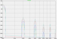
First, I took a somewhat different approach to preserving K2. First I simulated the output stage standalone with perfect inputs and adjusted it for the desired K2/K3 ratio. Then I adjusted the combination of local and global feedback (and various gain and offset adjusting resistors) in the front-end to preserve that K2/K3 ratio with enough global feedback to achieve a damping factor of around 150. This necessitated a very asymmetric local cascode feedback structure, but not significantly different in concept from that in your front end design. All of this was accomplishing the circuit topology shown in my .asc file. Here are the harmonic spectrum at 1W, 4W, 16W and 30W:
Attachments
By any chance to you also tease cats by dangling strings in front of them just out of reach?
No, I use a laser for teasing cats.
😎
If so, can this procedure be turned into a straightforward adjustment formula.
It's straightforward enough - we tweak, we measure, we listen. Eventually
we converge on something we prefer.
The original SIT-1 provided the exemplar, as the device has a rich set of
behaviors that are easily adjusted. We played with ways of making more
conventional circuits show some of the qualities we liked (and maybe not so
much some other qualities).
Anyone who wants to explore this approach is advised that a very good,
unvarying, sound system is essential and you need good ears and lots of
time.
😎

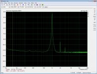
That looks like a no feedback SE triode tube preamp spectrum. If that's XA.8, stick I fork in me, I quit.
After hearing what Nelson said about the SIT-1 as a specimen for the other amps I am still more interested to hear a single ended amp with 2SK180. Mike did it already....
I hope that Mr. Pass will show his idea soon....!
🙂
I hope that Mr. Pass will show his idea soon....!
🙂
I can spoil any of yours perfect balanced amps , to sound as 90 yrs old SE one
back in OPLDF yard ......
https://youtu.be/ksmUVPyFYSQ

back in OPLDF yard ......
https://youtu.be/ksmUVPyFYSQ
That looks like a no feedback SE triode tube preamp spectrum. If that's XA.8, stick I fork in me, I quit.
Did you allready fetch a fork?😀
Attachments
That is a problem for me and maybe somebody has got a solution: Sometimes it is very difficult for me to get the Spice modells running. It takes hours. Afterwards I have no plan which files I changed to get it running. Because nobody else complained about these problems before, I thought I just didn't get it right. Solution would be, if sombody has got a (sturdy) workflow that describes how to create a stand alone version of the simulation files. The simulation modells I use are the common files that are freely available in the internet. Those without a copyright mark I put in the appended file.For the others please use internet search.I am having problems trying to run your LTSpice file XAleph0V12aMitGegenkopplungFinal2.asc because of missing library files for the Toshiba parts and perhaps others.
Attachments
- Status
- Not open for further replies.
- Home
- Amplifiers
- Pass Labs
- XA.8 single-ended current sources