gl said:Outstanding work gentlemen. Thank you for posting. This looks like it could turn into a great thread.
ACAUDIO: It looks like your schematic has twice as many MOSFETS as the PCB. Is this what you meant by "Passlabs use only a single set of secondary mosfets"?
GL
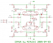
I use at present none compensations caps. I think a cascode how in Mr. Borbely designs can be useful for reduction of input capacitance. Maybe we should try this.
In Europe it´s middle of the night... 😱
Attachments
Based on a hint Nelson gave me while encouraging my development of my BZLS variation, I have a strong belief that the Jfets are indeed cascoded. That would definitely give the extended bandwidth needed to square up theat square wave. The question then becomes: Cascoded with what? Another Jfet seems unlikely, which leaves either mosfet or bipolar?
Hmmm....
Hmmm....
metalman said:... That would definitely give the extended bandwidth needed to square up theat square wave. ...
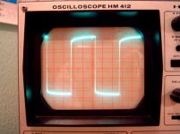
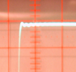
Now has it a little more contour, it was just a wrong (10x) probe from my oscilloscope.
It´s 1 kHz without compensation.
Regards
Adam
Attachments
let us go hot
Hi,
I played a little with the values, the frequency response is better (and distortion lower, hopefully) when the mosfets runs hot.
I changed the values from R6-R9 up to 10k, the diffpair bias is ~1,5mA . It gives aprox 15V at the mosfet-gate to supply,
Ug_abs-Ugs=URs -> 15V-3,5V=12,5V (URs) -> 12,5V/470 Ohm= 26mA
(U-URs)*I=P -> (30V-12,5V)*26mA=0,45W -> Ptot=1,3W ->😀
I tried too to measure CMRR, both input shorted to another and given a signal. At output ghostly still, no signal, it seems to work good. With my oscilloscope nothing to do.
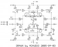
I removed (shorted) the R22, it´s wrong at place. At present I haven´t idea to correct the absolute offset (~500mV).
Here actually schematic:
Regards
Adam
Hi,
I played a little with the values, the frequency response is better (and distortion lower, hopefully) when the mosfets runs hot.
I changed the values from R6-R9 up to 10k, the diffpair bias is ~1,5mA . It gives aprox 15V at the mosfet-gate to supply,
Ug_abs-Ugs=URs -> 15V-3,5V=12,5V (URs) -> 12,5V/470 Ohm= 26mA
(U-URs)*I=P -> (30V-12,5V)*26mA=0,45W -> Ptot=1,3W ->😀
I tried too to measure CMRR, both input shorted to another and given a signal. At output ghostly still, no signal, it seems to work good. With my oscilloscope nothing to do.
I removed (shorted) the R22, it´s wrong at place. At present I haven´t idea to correct the absolute offset (~500mV).
Here actually schematic:
Regards
Adam
Attachments
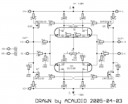
I added a 10k trimmer from R23-S to GND.
The absolute offset is now adjustable to 0mV, but the impulse response is worse than without the adjustment. ( little over swing by a square wave)
With a compensations capacitor (4,7p) no really better.
Mr.Pass, is this the right way for adjustment ? Should I use a higher value for comp. cap?
Regards
Adam
Attachments
You might want to try a trimpot between R1 and R2.....then again it might still be tricky to adjust............or replace R6 and R9 with trimpots.
Jam
Jam
jam said:You might want to try a trimpot between R1 and R2.....then again it might still be tricky to adjust............or replace R6 and R9 with trimpots.
Jam
I think this will not help. It would be next differential offset adjustment.
Adam
I thought about a silimar circuit a while ago, and these would have been my solutions :
1) Trim R8 / R9, which unfortunately affects the gain of the lower half.
2) Use separate current sources for the P and N diff pairs and trim one of them (for absolute offset).
3) Use two separate servos to feed current to R8 and R9.
Am not far enough yet to report actual experimental results.
Patrick

Cascoded with...?
Perhaps a folded cascode??
Like this?
I don't know why, (well, I'm a beginner) but I like these folded cascode designs. And it seems easier to me to control the open loop gain.
Sorry when I messed up the designations of the components. I'm in a hurry....oh, and I forgot the gate stoppers for the MOS-FETS
Later, Tino
metalman said:Based on a hint Nelson gave me while encouraging my development of my BZLS variation, I have a strong belief that the Jfets are indeed cascoded. That would definitely give the extended bandwidth needed to square up theat square wave. The question then becomes: Cascoded with what? Another Jfet seems unlikely, which leaves either mosfet or bipolar?Hmmm....
Perhaps a folded cascode??
Like this?
I don't know why, (well, I'm a beginner) but I like these folded cascode designs. And it seems easier to me to control the open loop gain.
Sorry when I messed up the designations of the components. I'm in a hurry....oh, and I forgot the gate stoppers for the MOS-FETS
Later, Tino
Attachments

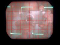
absolutely unbelievably! It works better with a single ended input than balanced. The square is now really clean.
Is this the trick for X2 design?
Adam
Is this the trick for X2 design?
Adam
This would be a BJT cascode design. What is the advantage of using MOSFET's as cascode transistors?
Doesn't BJT's keep the voltage at the emitter more constant than FET's while changing currents flowing through the devices?
Just thinking......
Ciao, Tino
Oh, Adam, sorry when I am always jumping in between discussion about your already working gainstage.....
Doesn't BJT's keep the voltage at the emitter more constant than FET's while changing currents flowing through the devices?
Just thinking......
Ciao, Tino
Oh, Adam, sorry when I am always jumping in between discussion about your already working gainstage.....
Attachments
zinsula said:Oh, Adam, sorry when I am always jumping in between discussion about your already working gainstage..... [/B]
Hi Tino,
maybe we should separate the thread in two?
Guys, what do you think about?
We can ask the Moderators. Only an idea.
Regards
Adam
Adam,
It will work since you mainly affect the gain open loop and the application of feedback will somewhat correct for this.
Jam
It will work since you mainly affect the gain open loop and the application of feedback will somewhat correct for this.
Jam
acaudio said:Hi Tino,
maybe we should separate the thread in two?
Guys, what do you think about?
We can ask the Moderators. Only an idea.
Regards
Adam
Hi Adam, for me it's OK, I have nothing against that 🙂
Anyway, Gute Nacht.
......or you might want to look at this.....on the other site..........for an implemention of a servo........thanks to Uli.
http://www.diyhifi.org/forums/files/pre5v3_648.pdf
Jam
http://www.diyhifi.org/forums/files/pre5v3_648.pdf
Jam
jam said:......or you might want to look at this.....on the other site..........for an implemention of a servo........thanks to Uli.
http://www.diyhifi.org/forums/files/pre5v3_648.pdf
Jam
Thanks Jam,
it looks very interesting, but I´m a minimalist. For me too much devices.
I like the simplicity of my circuit.
Tino,
You are right, it´s better one interesting thread as two boringly.
Gute Nacht
Adam
- Status
- Not open for further replies.
- Home
- Amplifiers
- Pass Labs
- X2_ugs3,4