They are North Creek Borialis, George Short was designing speakers for them and he was a very talented engineer. They use ScanSpeak drivers and he modified the D25 tweeter and designed the crossover. The construction was Baltic birch/MDF/ glop a combination of ncs glue and drywall. They ended up being about 60 lbs and finished in Birds Eye maple with 8 coats of lacquer. They have been my reference speaker, my living room now is a little small for them now and I am almost done building XRK’s XSD dipole speaker. It will be intersecting how it will compare. Thanks for such a great preamp, it sounds great, is dead silent a pleasure to use and the Headphone amp is a joy to my wife ( she can watch tv while I listen to music in the living room).
Bill
Bill

Bonsai,
What SSR do you recommend to use with the trigger? I built 3 fo- Felix line filter and a dc blocker, will these filters be ok in front of SMPS power supplies? It would be nice if the headphone amp plug interrupts the trigger to keep amps off when headphone listening.
Thanks
Bill
What SSR do you recommend to use with the trigger? I built 3 fo- Felix line filter and a dc blocker, will these filters be ok in front of SMPS power supplies? It would be nice if the headphone amp plug interrupts the trigger to keep amps off when headphone listening.
Thanks
Bill
Does the 12v trigger have a delay to turn on the amps? 2 of my amps have SMPS that have a 12 V trigger function built in. Another 2 amps have linear power supplies that need have the AC switched or build in a 12 switching function, either a SSR or relay. The worst that could happen with a relay would be the contacts fused closed and the amp would not shut off.
I should have gotten back to you on this - apologies.
The trigger output goes active 3 seconds after the amplifier comes out of standby - ie after you power it up via the remote or by depressing the Select dial.
When you put the preamp into standby, the trigger is deactivated first, and then 3 seconds later the preamp.
Typically, you would use the trigger output to drive a 12V DC 35mA DC coil current 16A 250VAC contact rating relay (like a good quality Tyco, Schrack or Potter and Brumfield industrial component - $3-4 on mouser) to switch the main amplifier power. Since you are switcing AC, the relay's are quite capable, although I would always recommend you use some sort of softstart.
I am not an expert on SMPS's (although I did design a few flyback types when in development decades ago), but presume on modern units mains DC offset is not a problem - the main issue is standard linear PSU's using large toroids. Rod Elliot has a nice discussion on this on his website.
Hope this helps
Regards
A
Yep I read his article and checked out his read on SSRs that’s why I figures in the long run a relay was probably the way to go. My linear power supplies all have soft starts so they are good. I think I will go with a good relay on the amp s ac outlets. I was going to add a dc blocker but the amp that hummed so bad was not the toroid but a low voltage mean we’ll power supply in it. Also a 5V and 12V power supply will help clean up mess behind amps.
Attachments

Hi Andrew, in the Phono board R1,2,30,34 are marked 270r on the board but on the Bom are marked up as 150r, which one I'd correct?

Hi Andrew,
Some more differences between Bom and board for for phono, C15,16,17 on the board printed as 1uf listed in the Bom as 1uf part number links to C0402C101J5RACTU which is a 100pf x7r 0402 footprint, which part is correct?
Chris
Some more differences between Bom and board for for phono, C15,16,17 on the board printed as 1uf listed in the Bom as 1uf part number links to C0402C101J5RACTU which is a 100pf x7r 0402 footprint, which part is correct?
Chris
On the HPA Board R23 and R14 are marked as 470r, as is the schematic but the BOM calls for 120r. Just want to confirm please
Chris/Andy
1. HPA-1 Headphone amp - R14 and R23 must be 470 Ohms as in the schematic and on the silkscreen; PCB and schematic are indeed 1N4148
2. MC/MM module - R1,2,30,34 are 270 Ohms. I will update the schematic and BOM; C15,16 and 17 must be 1uF devices 0805 same as C22 and C23 Mouser 187-CL21B105KBFNNNG or equivalent
I'll update the relevant docs later tonight.
Last edited:
Chris/Andy
1. HPA-1 Headphone amp - R14 and R23 must be 470 Ohms as in the schematic and on the silkscreen; PCB and schematic are indeed 1N4148
2. MC/MM module - R1,2,30,34 are 270 Ohms. I will update the schematic and BOM; C15,16 and 17 must be 1uF devices 0805 same as C22 and C23 Mouser 187-CL21B105KBFNNNG or equivalent
I'll update the relevant docs later tonight.
Thanks
Just working on wiring this all up, I have a question on the headphone board. Both the discrete line amp and Balanced boards have outputs for the headphone board, which one to use? To me the discrete line amp should be better, but I just want to confirm.
Andy, I've put output connection points on both boards for flexibility - some folks will not build the discrete board and others will only want the balanced board. The discrete board will drive the headphone amp no problem with low distortion so that will work very well.
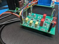
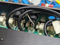
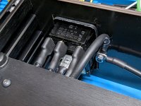
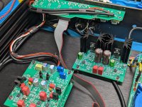
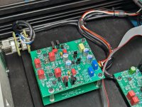
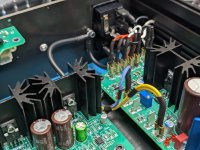
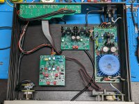
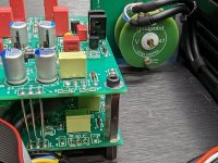
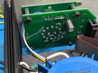
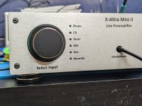
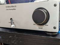
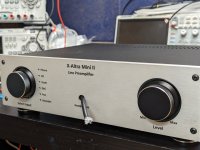
Misson (almost) accomplished 🔥 . Just waiting on the extra RCA jacks for the AUX and the headphone socket board to arrive. Wow it turned out amazing is all I can say right now. This project was not a small undertaking by any means, but the final outcome makes the last couple days of wiring worthwhile. I ran into a few hiccups here and there, but is to be expected with any project that has this many parts.
Thanks @Bonsai for another great project!! I can't wait to get my Phone preamps hooked up to this and get it all in my system. 😀
Thanks @Bonsai for another great project!! I can't wait to get my Phone preamps hooked up to this and get it all in my system. 😀
Attachments
-
 PXL_20230614_123126453.jpg538.8 KB · Views: 185
 -
 PXL_20230614_123142567.jpg558.7 KB · Views: 169
 -
 PXL_20230615_180958603.jpg420.4 KB · Views: 173
 -
 PXL_20230615_181257222.jpg366 KB · Views: 163
 -
 PXL_20230615_181304476.jpg381.3 KB · Views: 169
 -
 PXL_20230615_181325155.jpg543 KB · Views: 165
 -
 PXL_20230615_181332435.jpg502.6 KB · Views: 178
 -
 PXL_20230615_181343255.jpg447.6 KB · Views: 160
 -
 PXL_20230615_181357482.jpg654.6 KB · Views: 177
 -
 PXL_20230615_181413827.jpg506.6 KB · Views: 174
 -
 PXL_20230615_181426580.jpg381 KB · Views: 166
 -
 PXL_20230615_181432844.jpg477.5 KB · Views: 177
 -
 PXL_20230615_185152646.jpg483.9 KB · Views: 178
 -
 PXL_20230615_185159091.jpg333.1 KB · Views: 172
 -
 PXL_20230615_185212029.jpg303 KB · Views: 173
 -
 PXL_20230614_123107546.jpg436.8 KB · Views: 171
- Home
- Source & Line
- Analog Line Level
- X-Altra Line Level Preamp