It would be nice to try different op-amps and like the adapter Sparkos labs are offering -
DIP to SOIC Op Amp Adapter - Sparkos Labs, Inc.
However the price is silly so will use these 8 way connectors -
20021121-00008C4LF Amphenol FCI | Mouser United Kingdom
20021321-00008C4LF Amphenol FCI | Mouser United Kingdom
With brown dog PCB's without pins -
SOIC-8 to DIP Adapter - BrownDog Adapters - 970601
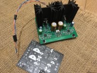
I had company this weekend, but the next steps are to head to the garage and start drilling and filing aluminum. I see I could have done slightly better with psu board layout to make my life easier, but it will all be good.
I want to add some feature to this amp, like symmetric inputs (through a balanced line receiver). So I plan to build my own board, is this allowed?
First I have to redraw the circuit, then add the additional features. I can provide the resulting schematics and board details, if it's finished.
Maybe someone can have a look, if I made some mistake(s) during redrawing?
Imgur: The magic of the Internet
First I have to redraw the circuit, then add the additional features. I can provide the resulting schematics and board details, if it's finished.
Maybe someone can have a look, if I made some mistake(s) during redrawing?
Imgur: The magic of the Internet
Maybe someone can have a look, if I made some mistake(s) during redrawing?
Imgur: The magic of the Internet
I haven't looked at it in detail, but it seems you are using EasyEDA. You might want to select a different OpAmp with identical pinout and footprint from the parts library, one that comes with the nice schematic symbols we all know for OpAmps (instead of these ugly boxes with 8 pins). You can search for OPA1642, that should give you the correct footprint with nice schematic symbols. The resulting schematic will be more structured and easier to check for mistakes. You can change the name to whatever you want after you placed the symbols.
Could somebody please come up with a TO -92 packaged transistor equivalent to the BC847C transistor in this project?
I am an old duffer that wants to build this circuit but doesn't want to deal with surface mount parts.
So suggestions? A T0-92 equivalent to the BC847C??
I am an old duffer that wants to build this circuit but doesn't want to deal with surface mount parts.
So suggestions? A T0-92 equivalent to the BC847C??
BC550C, BC547C, BC548C, BC549C.
Here is a quick video on how to solder SMD components
How to Solder SMD Components
I am also an old duffer and use 2.5+ specs when soldering. It’s easy - you should give it a go!
You need:-
1. Very fine tipped ( pencil tip) soldering bit
2. 0.5 mm solder wire
3. fine tipped tweezers
Without these basic tools you will not be able to put SMD down successfully.
(You can go the whole hod and get a hot air gun, solder past etc, buy for SOT23, SOIC, 1206, 0805 DIY work, the video shows the quick way to do it).
I dunno,
The few times that I've worked with SMD it felt more like work than a hobby. I find a certain elegance and satisfaction in thru hole construction that I just don't see with modern SMD. Perhaps that's yet more evidence that I truly am a cranky old codger that is past his prime. Ha, ha ...
The few times that I've worked with SMD it felt more like work than a hobby. I find a certain elegance and satisfaction in thru hole construction that I just don't see with modern SMD. Perhaps that's yet more evidence that I truly am a cranky old codger that is past his prime. Ha, ha ...
I'm a little curious as to why the schematic specifies +-18v for DC in but in writing you specify +-15 instead, any reason for that? 🙂
No - my oversight. If you are using LM4562, I believe they are spec’d at +-17 V. Most other GP opamps will do +-18 and some +-22V - the circuit will work ok with all these voltages.
+- 15 will cover most headphones.
The HPA-1 does not meet your discrete criteria, but it’s easy to build and gives very good results.
+- 15 will cover most headphones.
The HPA-1 does not meet your discrete criteria, but it’s easy to build and gives very good results.
I've decided to relax that criteria, as long as the opamps aren't doing the grunt work I'm fine with them 🙂
Edit: misread, rip
Edit: misread, rip
Last edited:
Bonsai, did you design an accompanying PSU board too? My parts for the TPA3255 amp are coming soon so it's time to think about actually purchasing the parts
I have designed a PSU that will power the headphone amp and the rest of the preamp I am working on but it’s not quite ready - some board corrections are needed. The PSU PCB does not incorporate the transformer. It will be some weeks before I respond the boards unfortunately.
Another question, would this case be acceptable in terms of heat dissipation if I sinked the transistors onto the side or bottom instead of using heatsinks? It's a really pretty case and I want to get one but it's internally only 45mm tall (I think) so the stock heatsinks would be a very tight fit.


- Home
- Amplifiers
- Headphone Systems
- X-Altra HPA-1 Class A Headphone Amplifier