Now I have shortened my layout down to 250x100mm. Distance between mounting holes on output transistors have decreased from 5 cm to 4 cm.
I have uploaded the current layout so you can see how it looks.
The silk screen has not been cleaned up, but I'll do that before the layout goes to print. Mounting holes, drill sizes and absolute placement of the two channels also needs to be sorted.
I'm open to suggestions and tweaks.
I have uploaded the current layout so you can see how it looks.
The silk screen has not been cleaned up, but I'll do that before the layout goes to print. Mounting holes, drill sizes and absolute placement of the two channels also needs to be sorted.
I'm open to suggestions and tweaks.
Attachments
Member
Joined 2002
Ok i'm going to set some prices up tomorrow evening. We should have prices setup for each to see..
The goal is to have a stereo set of boards per board, ie you ask for one board you will get 2 channels.
J'
The goal is to have a stereo set of boards per board, ie you ask for one board you will get 2 channels.
J'
It might be a good idea to call them "sets" and not "boards" in order to avoid confusion... 😉
The pdf I have posted contains both left and right side. The board is supposed to be split in left and right board between the fat output traces. And then you have one "set".
The pdf I have posted contains both left and right side. The board is supposed to be split in left and right board between the fat output traces. And then you have one "set".
Member
Joined 2002
I can't tell in the pdf, did you put snap lines on the board, that way the manufacturer will be able to put snamp lines in for us.
Member
Joined 2002
shallbehealed said:
Does a set include power supply?
I could include psu boards i'm currently working with briangt to make them a little smaller.
Please add me to the list for 2 "sets", including power supply boards ( if available ).
Thank you!
Tom
Thank you!
Tom
The design is based on my other board, A30, and has exactly same size and output devices spacing. So if if anyone built A30 with those PCBs, they can simply swap boards and use F4 in a same chassis now (adjusting transformer voltage may be required)
http://www.diyaudio.com/forums/showthread.php?postid=610637#post610637
http://www.diyaudio.com/forums/showthread.php?postid=613190#post613190
http://www.diyaudio.com/forums/showthread.php?postid=610637#post610637
http://www.diyaudio.com/forums/showthread.php?postid=613190#post613190
Hello,
I Like those Dale resistors you know the brown one's. Will they fit in the F4 board of yours Daniel ?.
gr Jaac
oh and another thing will they be beautiful black like those pcb's from BrainGT ??
I Like those Dale resistors you know the brown one's. Will they fit in the F4 board of yours Daniel ?.
gr Jaac
oh and another thing will they be beautiful black like those pcb's from BrainGT ??
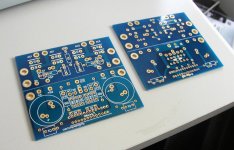
They will be beautiful blue, like in attachment. As to Dales, they will only fit in vertical position. I may consider going with full size resistors, but somehow those miniature resistors seem to fit here very well. And I was designing the board with a thought of using Caddocks or Vishays, that's why such small footprint.
Attachments
Member
Joined 2002
Sure, I can do them. The price per stereo set (amp boards only) should be approx $10.
I'm not tempted to offer PS boards, as most installations can be done p2p or using protoboards.
I can have the boards ready in 3 weeks or so (pending aproval from Mr. Pass).
I'm not tempted to offer PS boards, as most installations can be done p2p or using protoboards.
I can have the boards ready in 3 weeks or so (pending aproval from Mr. Pass).
I neeeeeed two sets!
Very pretty layout..
They are "tested" by the A30 boards as far as output device spacing dissipation, so I guess they won;t have heat issues despite being close together..
Very pretty layout..
They are "tested" by the A30 boards as far as output device spacing dissipation, so I guess they won;t have heat issues despite being close together..
- Status
- Not open for further replies.