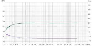
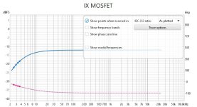
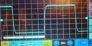
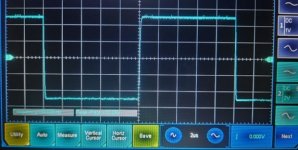
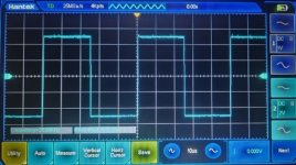
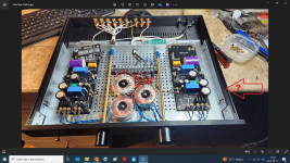
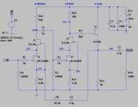
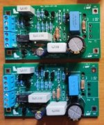
after few days listening adjustment, it comes to the final version of my DIY WOTS, in which ZVNL120A is replaced with 2xJ113. I tested bunch of J113 in my batch, Vdg is larger than 70V, so it is very safe to use them in the circuit. Also, from data sheet and my experiences, JFET is more favorite to me in preamps.
WOTS is really a wonderful preamp, if you don't mind its 0.2% pure H2 distortion at 1Vrms output. It really please me.

WOTS is really a wonderful preamp, if you don't mind its 0.2% pure H2 distortion at 1Vrms output. It really please me.
The chassis shown there is one of the Modushop by Hi-Fi 2000 "Slim Line" versions. The steel tray is the "Inner Base Plate for 280/350 Series"
Thank you for your reply.
I need a self-made box.
There is a front cover and a back cover I make myself.
This profile would make my job a lot easier
I need a self-made box.
There is a front cover and a back cover I make myself.
This profile would make my job a lot easier
Because my brain is not online, I connected the ground wire of one channel to B+. I just fixed it and haven't listened to it yet.🤣
@wwwtttwww
Thank you for appreciating and bringing the "WOTS Tre" to the highest level and verifying its good performance and sound!
Following your suggestion I developed the SGS (Shared Gain Stage) that is configurable as a line preamplifier (Talia) or as a RIAA equalizer (Vera) with the modification/addition of some components. But I am tempted to try the new "WOTS Tre", perhaps designing a PCB mechanically compatible with the SGS module to replace it on the mainboard.
I don't know what I will do.
For sure the next project will be a hybrid mu-follower, but I would also like to dedicate myself to a less mammoth (4 chassis) and less expensive power amp than the "WOTS WHA-53" (
https://www.diyaudio.com/community/...-a-hybrid-main-amplifier.396135/#post-7276068 ) leaving its circuitry unchanged, trying to house it in two chassis: 2U for the front-end and 3U for the power buffer.
Ciao!
You obtained a non-inverting preamp but you had to use the feedback to lower the gain suitably to a line-level preamp. Consequently, the THD is a lot lower.
I'm sure you'll like better the Tre's sound.
All my project work without feedback, this is a must I have imposed on myself.
Since I love to experiment, I suggest the following simulation:
divide Rd2 (30KOhm) in 2 x 15KOhm and connect their midpoint to J5's source with 2.2uF or so. You obtain a bootstrap for the second stage which is supposed to lower the already outstanding THD.
You can try the same sim with the Tre. After simulating, it will be easy to apply the bootstrap in the real thing on the fly. If you plan to try it, please let me know about the "new" sound.
what is the highest output voltage with reasonable distortion?
will wots tre drive an F4 (buffer)?
will wots tre drive an F4 (buffer)?
I don't think so. You should use a higher voltage to have a clean 20Vp at least to drive the F4 with the Tre. Look at the SGS in my post #57, which is modifiable to 100V voltage and has a better THD with the Sziklai option. I cannot run the sim on this computer, I have something missing and it doesn't work.
I was able to make some Sims, and the SGS seems to be not good to produce a clean 20Vp, not even with 100Vdc. It was conceived as a RIAA eq and as a line preamp. I think the same is valid for the Tre. Sorry! To have such a signal voltage with one only gain stage is better to use tubes.
thank you for simulations and advice.
I don't need the full power of F4,
would 10Vp be achievable with Tre or SGS Sziklai?
I don't need the full power of F4,
would 10Vp be achievable with Tre or SGS Sziklai?
I'm sorry, but the LT Spice setup or the LSK489 model I have on this computer seem to have problems. Do not even take my last post into account. My other computer is far, I don't know when I'll be able to use it again. Member wwwtttww can help.
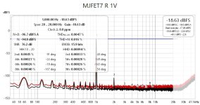
I like more H2. MJFET7 is just for fun and testing. For its configuration(extremely large Rs1 and Rs2, extremely Small Id1 and Id2) , my goal was try to minimize THD, it was successful. The sound is not lively as WOTS.
Next step I might try to increase Id1 to 1mA and Id2 to 4mA(WOTS) level. In the sim, THD becomes bigger, but H2/H3, too.
Next step I might try to increase Id1 to 1mA and Id2 to 4mA(WOTS) level. In the sim, THD becomes bigger, but H2/H3, too.
I can achieve 10Vrms with WOTS in Sim and in Practice without any problem. The Vp will be 14V.thank you for simulations and advice.
I don't need the full power of F4,
would 10Vp be achievable with Tre or SGS Sziklai?
- Home
- Source & Line
- Analog Line Level
- WOTS Pre-amplifiers
