I found the same thing here, 8K push pull 5W output transformer, frequency response 12HZ 45KHZ 3DB, suitable for 6C16 5842 5686 and other tubes|Transformers| - AliExpressI love the wheels!
I'm bad about over analyzing choices so I'm going to post a few transformers to get some feedback.
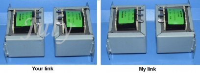
A rather sketchy looking one - the pictures make you think pair but I think the price quoted is for one
They say "Quantity: 1 + 99 Pair available" look as they go in pairs.
With outputs 2Ω and 4Ω on the connections 4 and 8Ω you get Raa=4k.
Transformers with 3wire 110/220V are not symetrical.To use it as an OPT you need 2x 115V, series 230V and parallel 115V.For the two 115V to be paralleled they have to be identical.
Mona
That's not quite the same thing though. The one I listed has "Amorphous dual C-type iron core" while the one you listed does not. By saying they are the same you might be saying that those words are meaningless marketing. If so I appreciate the feedback. Actually I thought that one was too expensive compared to other options but I had to post it because I'd never seen a transformer held together by a hose clamp.
I figured that the 0-110-220 inputs must not be symmetrical but given some of other things I have seen in listings I decided to ask just in case. Thanks.
I figured that the 0-110-220 inputs must not be symmetrical but given some of other things I have seen in listings I decided to ask just in case. Thanks.
My Corean is not so good 😀 so I only look at the pictures.And I don't see much difference 😕That's not quite the same thing though. The one I listed has "Amorphous dual C-type iron core" while the one you listed does not. By saying they are the same you might be saying that those words are meaningless marketing.
Mona
Attachments
No problem - you quoted my link to the oddball one but replied to one of my other links! Nice find though but it slightly confused me.
It's been longer than I planned to get a schematic up but then again I am waiting on things to arrive (and I waited for the late Nov. sale)
The current plan is a SMPS outputing +- 48V (plus a single 12V that will be used for negative bias) and a buck converter to produce the heater voltage (actually two to make sure that they stay under their rated current).
Push pull with 12CA5 tubes. PP seems to be a clear winner at this size especially with the low B+. 12CA5 has a higher load resistance than the 12C5/CU5 so it matched the transformers better. Plus it looks like I could swap out for the 12C5 later if I wanted more power. One compactron per channel as the gain and inverter. I could have used any of a number of twin triode tubes but the 12AC10 was cheap and more or less equal to a 12AT7 (and a half). Plus I kept looking at LTP circuits such as Peter Millett triple triode driver but, after ordering, I decided to go with a simpler split load PI following Matt Robinson so each channel has an unused triode.
All resistor and capacitor values are open to change. The OTs are 8k to 8 Ohm 15W ones from China similar to the ones mentioned earlier in the thread. No ultalinear mode but if I need to I can wire in the unused triode stage and give even more room for negative feedback.
Attachments
Hmm, I'm not sure whether to take the silence as a sign of ok but boring design or being so far out of whack that no one wants to be the first to touch it!
The 12CA5 does not look very linear under 100 volts. How were you planning on fixing the bias?
What happened to the space charge tube thinking?
Did you see this thread?
PL504 low voltage amp
What happened to the space charge tube thinking?
Did you see this thread?
PL504 low voltage amp
Last edited:
With voltages and currents so low it's rather difficult to know if it will function correct.R5 and R8 probably to be adjusted and different for any another tube.Hmm, I'm not sure whether to take the silence as a sign of ok but boring design or being so far out of whack that no one wants to be the first to touch it!
Only the bias -5V I think and an output perhaps just over 1W.
Mona
The 12CA5 does not look very linear under 100 volts. How were you planning on fixing the bias?
The SMPS also comes with a +-15V output that I should be able to use to provide negative bias. The data sheets suggest around -3.5 or -4V so voltage divider.
What I'd like is the 12EH5. It looks a little more linear and might have a slightly better load resistance. But at least three different stores only sell 12CA5/12EH5 without distinguishing. So, since I could get 10 for less then 4 of anything else I figured I'd go for it as a learning experience. Most of the expense is in the chassis and OPT so I don't mind playing a little with the tubes.
Did you see this thread?
PL504 low voltage amp
Yes. I'm stubborn and hate following a design or recipe without playing around with it. 🙂 It looks good and clearly gets great power for the voltage input but, for better or worse, I want this amp to be a push-pull one. I have thoughts bouncing around for a SE amp also but not until the PP is pushed out of the nest.
The space charge (and some of the Soviet lower voltage submini tubes) are still bouncing around in my head. But it is clear that the students are not going to be back in any sort of extracurricular mode until at least next fall.
Following up on my comment about not normally following designs or recipes without modifications. One thing I've learned over the years is that I learn best by talking things out. Sometimes I can talk to myself but that often ends up with odd results.
From a pure data sheet look that 12CA5 states lower distortion than most other output tubes and 1.1 watts power (SE) at 110V. I'm trying to end up around 85% of that voltage so low but not outrageously lower than the designed values. Conservatively 70% of the listed power and then double it for PP (not exactly but close enough for this work) to end up with just over 1.5W per channel expected output.
R5 is clearly too large. That value was simply used as a placeholder because I wanted to put some sort of schematic up. My first, still very rough, idea is to drop it to either 47k or 100k.
R8 is less clear to me. The idea of the PI circuit makes sense but I haven't had a chance to either sit down with numbers or compare to a known circuits with a similar PI and B+ to give better starting values. So again I put in placeholders while I go off to do more calculating. That's actually why the resistors and caps aren't ordered yet. Plus I can get them locally and thus quicker.
The current thru R8 sets Vgk. You need a set of curves in front of you, and a target for the plate current, in order to calculate it.
I wouldn’t just order a handful of very specific resistor values. I’d think about a resistor kit if starting from scratch here - resistor values are always subject to change as a project matures. Even if you’ve done it before.
That phase splitter does not have a lot of voltage to work with. I would still look at the LTP as a possibility - especially if you’re considering a transistor CCS. Build up both and try them - see how much undistorted voltage swing you can actually get out of them before committing to a final design. My guess is you’ll need about 12V p-p. That concertina might have a hard time delivering even that.
LOL! You are certainly right about resistors. Ordering was more of a verbal shorthand. I'll actually be purchasing capacitors, switches, the fuse, and similar things locally. Anything below a 1W resistor I'm likely to have on hand.
Only the bias -5V I think and an output perhaps just over 1W.
I think you are right on the bias. While the data sheet gives -4V at 110V plate and screen voltage(and -4.5V at 125V) it looks to my novice eye that it would be better to bias at roughly -5. That looks like a swing of slightly over 160V peak to peak in PP for a 10V peak to peak input with an 8000 Ohm transformer load to give 1.6W.
I do sort of question this. Biased at that point with plate and G2 at 96V it looks like a 10V peak to peak signal will stay firmly in class A. At -10V on the grid the tube isn't shut off yet. Maybe that isn't something to worry about?
Attachments

Yes, if you bias too high you will lose power. When biased in class A, where both tubes are providing transconductance over the entire cycle, the load resistance is half Ra-a. The load on each tube is 1/4 Ra-a, but with two in parallel R doubles. When one tube cuts off, it transitions to 1/4 Ra-a, increasing the current swing in the active tube. You get a “kinked” load line, but only if you drive hard enough to cut the lower tube off. It’s not a sharp transition, it happens gradually as one tube loses transconductance (curves getting bunched up at the bottom) and the other still has plenty. Somewhere there is an optimum bias for best overall linearity (where the composite gm’s tend to be more constant) - it may not be the same as for optimum power. Low voltage amps tend not to be the most linear because of so many other constraints, one of which is to get a useable amount of power.
@Ketje - fair enough. That makes sense and is why I did the rough power scaling that I mentioned earlier (I was fully expecting to see about 0.7 W per tube based on a purely V squared rule that works very well given the two operating points I have found on most data sheets).
@wg_ski - Thank you. I think you might have cleared up one thing even if you have raised some other questions.
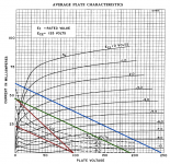
First, if I re-draw the load curve using the values from the data sheet (V plate and screen at 125, plate current of 32mA, load of 4000 Ohms) and biased at -4.5V. I didn't fire up Gimp again to shift the line but a rough guess says that leads to a minimum voltage around 24V with a max current of 60mA. Using the power output calculators from a couple of sites that talk about drawing load lines that would indicate more like 3W max power when the data sheet says 1.5W for those conditions. Are these sites just being way too simplistic by calculating power as (HT - Vmin)*Imax/2? Note that I'm not worried about distortion (right now) and whether it is a good idea to run all the way to cutoff; that will come later.
Sort of 1.5. Related to the calculations I did yesterday and the rough stuff in the last paragraph it seems like I might simply have the wrong idea of a good zero signal plate current for push pull operation. How does one chose this given that the data sheets almost invariably give only SE operation data?
Second, can I ask for clarification due to the negative sign. By higher bias do you mean closer to zero or larger absolute value?
@wg_ski - Thank you. I think you might have cleared up one thing even if you have raised some other questions.
First, if I re-draw the load curve using the values from the data sheet (V plate and screen at 125, plate current of 32mA, load of 4000 Ohms) and biased at -4.5V. I didn't fire up Gimp again to shift the line but a rough guess says that leads to a minimum voltage around 24V with a max current of 60mA. Using the power output calculators from a couple of sites that talk about drawing load lines that would indicate more like 3W max power when the data sheet says 1.5W for those conditions. Are these sites just being way too simplistic by calculating power as (HT - Vmin)*Imax/2? Note that I'm not worried about distortion (right now) and whether it is a good idea to run all the way to cutoff; that will come later.
Sort of 1.5. Related to the calculations I did yesterday and the rough stuff in the last paragraph it seems like I might simply have the wrong idea of a good zero signal plate current for push pull operation. How does one chose this given that the data sheets almost invariably give only SE operation data?
Second, can I ask for clarification due to the negative sign. By higher bias do you mean closer to zero or larger absolute value?
If you assume you are running fully class B, the most voltage swing you could expect is about 70 volts. With an 8k CT transformer, the class B load line is 2k, giving 35 mA of current swing and 1.25 watts of power. To get that much, you would have to bias well under 1/4 of that. Linearity might be pretty poor, and biasing up at 17.5 mA would result in a 4K ohm class A load line, and half the power. You might be better off (in this application) getting a 4K a-a transformer instead of 8k, and plan to run in class A push pull up at 35 mA or so. These things are usually run single ended, with a 2k load, when operating off 110 V B+.
According to the data sheet they are designed to run SE into a 3.5k at 110 B+ (or 4k at 125) so yes I am looking to run what is likely to be fully class A PP. Logic suggests that I can't shift the load line infinitely far to the right so I have the green curve that would need to be biased to around 24mA. This might have problems on the negative swing but it's PP so the other side will be working well.
The blue curve is great and the Valve Wizard doesn't say anything against it but I don't see how the inductance of the transformer can supply that much voltage. If it can a bias of -4ish looks good.
Clearly I'll be putting a pot on the biasing voltage divider to play around with different values! BTW, these things have a 5W dissipation so the blue curve stays under 70% of it at all points.
Attachments

- Home
- Amplifiers
- Tubes / Valves
- Workshop Audio Project - low power intro to playing with tubes