Interious
Sorry for the poor photographs, my camera is an older digital and not very good for closeup work.
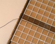
The sliding end pieces have small horizontal pegs near the top the same diameter as the Kynar wirewrap .035" . There are 5 pegs /louver opening so 10 wires/louver square.Loop the wire around the pegs at each end then then tighten the screws on the sliding end piece to pull the wires tight.I had the jig built by the machine shop next to my office about 5 yrs ago in return for some computer work.Here is another picture with a white piece of paper in the background so you can see the pins.
I think I would cut up the plastic louver so that there would only be horizontal plastic squares about every 3".I would then glue a piece of PVC about 1/4" wide by .020 thick to this row of squares.That would give me something more substantial to attach the wires to.Plastic PVC glue might work for attaching the wires to the plastic strips.
Andrew
Sorry for the poor photographs, my camera is an older digital and not very good for closeup work.
The sliding end pieces have small horizontal pegs near the top the same diameter as the Kynar wirewrap .035" . There are 5 pegs /louver opening so 10 wires/louver square.Loop the wire around the pegs at each end then then tighten the screws on the sliding end piece to pull the wires tight.I had the jig built by the machine shop next to my office about 5 yrs ago in return for some computer work.Here is another picture with a white piece of paper in the background so you can see the pins.
I think I would cut up the plastic louver so that there would only be horizontal plastic squares about every 3".I would then glue a piece of PVC about 1/4" wide by .020 thick to this row of squares.That would give me something more substantial to attach the wires to.Plastic PVC glue might work for attaching the wires to the plastic strips.
Andrew
Andrew--
I see, very clear. Have you succesfully built stators with this jig? How do you execute glue application? I like the idea of enlarging the openings and gluing a more substantial footing on for the glue interface.
Yes--I see it exactly, an excellent idea that never occured to me. I'm trying to think if 0.035" wire (20#) is stiff enough to span 3". The ductile copper seems to loose any tension induced in the wire. What do you think?
Dave
Are you able to retain spacing uniformity along the length of the stator with this method?
Dave
No, I haven't built a finished stator with the stretcher.After the first try at gluing the wire to the plastic frame I came to realize that the strecher works as I envisioned it would but there had to be a better way to glue the wires to the frame. So I put the whole thing on hold while I thought this out. I had plenty of other projects to keep me busy .I just started working on this recently again after I purchased the electronics c/w delay lines from an ESL63.
I think that the spacing would remain constant ,if not then maybe reducing the support to 2 " may work.The glue application would be a little easier with the wider supports a plastic type glue and a brush type applicator??
Andrew
Mmmm...Good question. I would probably use epoxy applied with a syringe and use a heat gun to partially liquify the glue, causing it to flow,
but I'm unsure of bond strength to PVC.
I've only used plexi or lexan for spacers (thinking or your supports) in the past, but the thickness tolerance is notoriously poor. Whether that is audible is a difference question.
The arrangement of you stator/diaphragm spacers will be a consideration.
I'm sure others will comment.
Dave
Excellent idea!I_Forgot said:
If you have a vacuum pump you could borrow a technique from composite lay-up and vacuum bag the assembly to apply pressure while the epoxy hardens. A small diaphragm pump can easily pull about 20" Hg vacuum which translates to 10 lbs per sq inch over the entire surface. Model rocket and airplane guys often use vacuum food sealers for this job.
I_F
Dave and all- there are adhesives specifically made for specific plastics. Once you've bought your frame or eggcrate, buy the adhesive specific to that material. Here in California, TAP Plastics and the always-reliable McMaster-Carr are good sources for those specialty materials.
Some examples:
http://www.tapplastics.com/shop/category.php?bid=21&
Some examples:
http://www.tapplastics.com/shop/category.php?bid=21&
Hi,
After my experiments with steel sheet stators , i have found that it is very hard to paint a good and reliable insulation layer.Even powder coating+few layers of paint does not provide good enough insulation.
So i decided to build wire stators.I am planning to build frames from 15mm plywood.Also , i found some very cheap 0,5-1,0 mm^2 PVC insulated wire.My question is , at what distances the wires must be supported ?
Is 10 cm enough ?
Regards,
Lukas.
Roughly, anything between 7,5 and 15 cm will work fine. It is not that critical.
I personally prefer a rather close spacing of around 8 cm in case of flexible 'litze'wire because this type of wire tends to wrinkle a bit.
Cheers, Martin-Jan
I personally prefer a rather close spacing of around 8 cm in case of flexible 'litze'wire because this type of wire tends to wrinkle a bit.
Cheers, Martin-Jan
Hi,
The wire is a single wire.I was looking for it because i think it is less flexible.I can chose thickness of 0.8 or 1.2 mm(internal copper diameter).Which is better ?
Also there are black or other colors.Does the color affect insulation strength or conductivity ?
Thanks ,
Lukas.
The wire is a single wire.I was looking for it because i think it is less flexible.I can chose thickness of 0.8 or 1.2 mm(internal copper diameter).Which is better ?
Also there are black or other colors.Does the color affect insulation strength or conductivity ?
Thanks ,
Lukas.
I’ve been following this thread for awhile, and sketching ideas, and I have a few lingering questions I was hoping someone could help me with.
1) Wire diameter and insulation thickness: Does anyone know if the insulation on PVC-insulated wire is of the same thickness regardless of the diameter of the conductor? I’m concerned that if I use very fine wire for stators, the ratio of insulation thickness to conductor diameter will start to become too large. For the sake of argument let’s say 50% open area is the goal (and I’ll use open area to refer to the fraction of the area covered by the conductor, rather than by the conductor plus its insulation). If small gauge wire is used for the stators then many wires per cm will have to be used to achieve 50% open area. Won’t the gaps between the insulation on neighboring wires start to become blocked by the insulation? Or, to put in another way, if sufficiently large gaps between the insulation on neighboring wires are achieved, doesn’t it become hard also to achieve a 50% open area? If the insulation on smaller diameter wires is thinner that would help solve the problem but wouldn’t that make them more prone to arcing? Seems like trouble either way.
2) Is there a consensus on using solid rather than stranded wire for stators? I would think it would be easier to pull the kinks out of stranded wire but are there other issues to contend with?
3) I’ve been trying to think my way around the issue that Dave described well: unequal tension on wires. My impression is that others have not resorted to the “hooks on rubber bands” method that he used. My own reasoning was leading me down Dave’s path, but I share his lack of enthusiasm for overly labor intensive approaches. Can others report success with other methods? In case it matters, I really don’t want to use the fluorescent light louvers but I’m worried that the result will be even more vulnerable to wire tension problems.
Capaciti: It appears you’ve come up with a method that works; can you share your technique? However, 96 wires for 0.78” cell width?! How long does it take to make a stator?
Thanks in advance for any ideas or insights anyone can provide.
Few
Hi Folks,
1- dont use stranded wires. The wires are internally wrapped like a thread. as time goes by, the wires tend to unscrew, getting straight and as a result will lengthen, means will loose initial tension.
2- pvc is material of choice. use black wires only, others insulation will get briddle by time due to coulour pigments.
3- the smaller the stator-membran distance, the closer the distance of wire to wire (center-center) need to be. otherwise you will increase area without sufficient electrical field. 2,2mm OD wire (1,6mm copper) is OK for distance 3-4mm. Capaciti-ESL use 1,1mm OD wire for 1mm distance.
4. thickness of insulation isnt critical as long you build hybrids, which require much less stator voltages compared to fullrange -esl. be careful with wire supplier. some use lousy pvc, which might show microcracks after a few years.
5. copper quality is important regarding stretching the wires. harder alloy will crack before sufficient tension is applied.
6. we developed a gig, which enables us to wind and stretch the 96 wires within 7-10 minutes. you need to understand that i cannot share how it works. we are dealing esl and thats what we are living from.
summary: if you can use wire- it will outperform a sheet metal stator by far. Higher efficiency, no sparks under any condition, safe if you touch it, if supported properly the flatness is incredibly perfect und at last it gives you the option for segmenting.....
capaciti
Thanks for your helpful reply,
How do i find out if PVC insulation is lousy ? By the way , it is rather thick , around 0.5mm.
Also , do you think it is good to use 2mm outer diameter(0.8mm copper) wire for diapraghm - stator spacing of 1.5-2mm ?
Lukas.
How do i find out if PVC insulation is lousy ? By the way , it is rather thick , around 0.5mm.
Also , do you think it is good to use 2mm outer diameter(0.8mm copper) wire for diapraghm - stator spacing of 1.5-2mm ?
Lukas.
Thanks, Capaciti, for the response. It's quite helpful. I certainly understand your need to keep your jig design "close to your vest", as they say. Can I ask for some clarification? I'm interested in ~1mm stator-diaphragm spacing so I'm interested in the wire you suggested. You mentioned 1.1 mm OD; is that the OD of the insulation or of the conductor? If it's the insulation, what is the OD of the conductor?
Also, if you've had success with a particular wire manufacturer could you mention who that is? Again, I understand if you consider that information to be proprietary.
Thanks again for the assistance. You've inspired me to continue the design process with renewed enthusiasm!
Few
Also, if you've had success with a particular wire manufacturer could you mention who that is? Again, I understand if you consider that information to be proprietary.
Thanks again for the assistance. You've inspired me to continue the design process with renewed enthusiasm!
Few
Capaciti said:
The wires i use are very thin (0,0035") and open area is 50%. This requires 96 wires for 0,78" cell width.
capaciti
Capaciti said:
3- the smaller the stator-membran distance, the closer the distance of wire to wire (center-center) need to be. otherwise you will increase area without sufficient electrical field. 2,2mm OD wire (1,6mm copper) is OK for distance 3-4mm. Capaciti-ESL use 1,1mm OD wire for 1mm distance.
capaciti
Dear "capaciti",
I'm a little confused on the wire size you use. From the two statements above ( from posts #18 and 33 ) the 1.1 mm OD in post 33 would be .0433 inches while post #18 states .0035 inches and the 96 wires per .78 inches which is approximately 10 times smaller. Also the coin in the picture in post# 18 appears to be about 14 wires and spaces wide which I think would be more in line with the 1.1 mm wire size.
Please correct me if my math is wrong or if I am missing something, but would you please explain the apparent differences?
Regards,
Tom
PS. Thank you for your contributions to this forum!
interjection
This is a suggestion for those working with light louvre (egg crate) as a base for wire strung stators. I suppose that one could also use this idea for other similar methods.
To start the base of this idea is use a auto plastic primer as an adhesive, for those who may not have known there are a number of paint primers used in the aero space industry as adhesives. Primers come in two varities being "low build" and "high build". This refers to the amout of film thickness you can "lay" in a single pass of the spray gun. "High builds" are useful in repair and layering jobs. In this instance you want to use a "low build" type which are typically a couple of mil (thousanths of an inch) per wet coat (thin). These can also be found in clear versions. The louvre should be prepared by a light sanding or scuffing with a 3M scrubby pad to remove mould release agents and to enhance surface area. Coat the louvre with a wet coat of the "low build" clear primer and let dry (quite fast). String your stator wires on the jig if your choice. Insure that the wires make firm contact with the louvre and then spray again with the primer. Two or three wet coats (one at a time) should do just fine. This will then encapsulate the wire onto the surface of the louvre without clogging up between the wires. I should think that you could even experiment using the primer as an adhesive for stator spacers.
I hope that this is of some interest to those who have an interest to build an Acoustat style panel. My preference there is to use double build magnet wire or Kynar wire wrap wire in the 28-30 gage size rather than the much larger PVC dielectric insulated wire as the high strength dielectric wire premits very many times more wires per inch than the large PVC versions. This primer will work very well on PVC dielectric insulation though for those whoses preference leans in that direction. Best regards Moray James.
Hi,
@tommak,
you are right, 0,0035" is wrong. i made a mistake by converting 1,1mm to inch. I did not use an calculator. 0,043" is the right size.
capaciti
@tommak,
you are right, 0,0035" is wrong. i made a mistake by converting 1,1mm to inch. I did not use an calculator. 0,043" is the right size.
capaciti
Re: interjection
Hi,
Thanks for suggestions.But , don't you think that 0.5mm PVC insulation will have higher dielectric strength , so higher bias voltages would be possible ?
Also , I think, the support points can be farther away for thicker PVC insulated wires.
I would like to ask , what size of wire acoustat uses , and what is their d/s spacing ?
Thanks in advance ,
Lukas.
moray james said:
I hope that this is of some interest to those who have an interest to build an Acoustat style panel. My preference there is to use double build magnet wire or Kynar wire wrap wire in the 28-30 gage size rather than the much larger PVC dielectric insulated wire as the high strength dielectric wire premits very many times more wires per inch than the large PVC versions. This primer will work very well on PVC dielectric insulation though for those whoses preference leans in that direction. Best regards Moray James.
Hi,
Thanks for suggestions.But , don't you think that 0.5mm PVC insulation will have higher dielectric strength , so higher bias voltages would be possible ?
Also , I think, the support points can be farther away for thicker PVC insulated wires.
I would like to ask , what size of wire acoustat uses , and what is their d/s spacing ?
Thanks in advance ,
Lukas.
As I mentioned in a previous post, I'm trying to determine the best combination of PVC insulation thickness, conductor diameter, and wire spacing. I'm working with a 1 mm gap between the wire's insulation and the diaphragm, just to standardize on a reasonable value.
I drew up a scale diagram after locating some possible choices of single conductor, PVC insulated wire. I found it interesting so I thought I'd share it with others. In the diagram I've been careful to draw the conductor diameter (the central dark spot) and the insulation surrounding it, all to scale. The diagram, in pdf format, can be found at:
http://abacus.bates.edu/~mcote/Audio/wire_stator_dimensions.pdf
The bulk of the diameter of the 30 gauge wire (insulated for a 300V rating) consists of insulation, rather than the conductor. I haven't yet done the calculations, but it seems clear that while I've drawn all three cases to achieve 50% open area when the insulation is taken into account, they have quite different values of percent open area if the conductors are the only consideration.
Perhaps those who have already built wire stator ESLs are in the best position to point out the pros and cons of each of the scenarios I've drawn. Nonetheless, I'll risk voicing a preference. Unless the 1000V rated insulation is necessary, I find the 24 gauge wire with 300V insulation to be an attractive option. It would certainly be cheaper than the 30 gauge version, especialy since the 30 gauge version would require more feet of wire for the same size stator.
Few
- Status
- Not open for further replies.
- Home
- Loudspeakers
- Planars & Exotics
- Wire stator gluing method