Hi all,
I'm planning a new wire-ESL project and I'm at an impasse trying to find the preferred wire.
I have a stator design and a wire stretching jig setup and spaced for
.054 diameter UL 1429 20AWG single strand wire with .010 irradiated PVC insulation, which I've used on prior builds. However; I am now unable to find that wire unless I'm willing to do a 40,000 foot min-buy (and I'm not).
I came across a source for 20 AWG single strand UL 1061 appliance wire of similar diameter, but I'm unsure about the electrical properties of the semi rigid PVC insulation.
Has anyone tried the UL 1061 wire for ESL's?
I have used semi-rigid PVC insulated wire in the past. It is not quite as abrasion resistant as the cross-linked irradiated PVC, but still rugged enough in my opinion. The biggest issue I had was soldering to it since it will melt and shrink back when heat is applied to the wire. If you use crimp connectors or can deal with this using heat sink clamps during soldering I think you should be fine.
One other think I just thought of is that the semi-rigid PVC is still a thermoplastic while the irradiated PVC is a thermosetting material. This may change the bonding strength with different adhesives. You may want to purchase a small amount to see if the adhesive you have been using(E6000?) bonds well to the semi-rigid PVC.
One other think I just thought of is that the semi-rigid PVC is still a thermoplastic while the irradiated PVC is a thermosetting material. This may change the bonding strength with different adhesives. You may want to purchase a small amount to see if the adhesive you have been using(E6000?) bonds well to the semi-rigid PVC.
Thanks for the tip, Steve. Although the semi-rigid PVC insulation is a bit glossy (no shine at all on the XLPVC), I've just confirmed that the E6000 glue will adhere to it.
If you have any surplus electronic stores in your area, you might check them out on the slight chance that they will have a spool of your preferred wire choice.
I had pretty good luck using UL 1061. I don't have anything else to compare it to, but I was very happy with the result.
I had pretty good luck using UL 1061. I don't have anything else to compare it to, but I was very happy with the result.
That's great news... thanks.
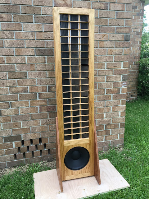
I will find out for myself in a few weeks. I'm well underway building four pairs of my Audi speaker design (photo below), and I've just received a 3,050 meter min-buy of 20AWG UL-1061 wire from China. It looks very nice-- can't wait to string it up in my stretching jig and get some stators built.
Hey guys,
I’m very inspired by Charlie’s build and I’m trying to plan for the build. I have a question, will 1007 #20AWG, PVC insulated, tinned copper wire, single strand be a good replacement? It seems not quite economical for me to get 1061 as it about 2x the price.
Thanks,
Terence
I’m very inspired by Charlie’s build and I’m trying to plan for the build. I have a question, will 1007 #20AWG, PVC insulated, tinned copper wire, single strand be a good replacement? It seems not quite economical for me to get 1061 as it about 2x the price.
Thanks,
Terence
Hey guys,
I’m very inspired by Charlie’s build and I’m trying to plan for the build. I have a question, will 1007 #20AWG, PVC insulated, tinned copper wire, single strand be a good replacement? It seems not quite economical for me to get 1061 as it about 2x the price.
Thanks,
Terence
Unfortunately; I unwittingly chose a difficult to find wire for my stator design. Interstate Wire had some 20awg single strand UL-1429 at the time, and at a good price, so I went with it-- thinking it would be readily available in the future without a min-buy requirement.
Open area percentage and wire size <d/s (<.063) drove the wire choice in my design. I had read somewhere that Panasonic Corp did a study on ES tweeters wherein they determined that 42% open area gave the highest output efficiency, so 42% became my goal.
If you want to change the wire size but retain about the same open area, you will have to step-down the wire gauge if you use anything other than UL-1429 or UL-1061. Also; if you step down the wire gauge, you will need to space the horizontal wire supports closer together-- there are some guidelines on my blog for this. You may also have to adjust the width dimension of the panel to accommodate an alternate wire size.
Jazz
hmmm it seems like if i use ul-1007 i'll have to change a couple of the things in the design, which doesn't seem like something i'd love to do. I would love to try it keep it as close as your build if possible. I guess i'll try harder to hunt for some ul-1061 or ul-1429.
Out of curiosity, I believe the wire size & length would affect the impedance/resistance. How does one go about calculating this? Or it is not important give that the source from the amplifier will be further stepped-up by a transformer?
Out of curiosity, I believe the wire size & length would affect the impedance/resistance. How does one go about calculating this? Or it is not important give that the source from the amplifier will be further stepped-up by a transformer?
Is it also a must to use single strand? any reasons for it?
Stranded wire would work but I recommend single strand because the wire is not tensioned in my design, and single strand holds itself straight (after it has been stretched to 1% elongation and then relaxed).
Regarding your question about wire resistance/impedance:
If you were to unwind one of those 230V/260V transformers feeding the stator, and see the hundreds of feet of hair-thin wire used in the 230V windings, I think you would then feel confident to disregard the resistance of the stator wires 🙂
BTW; Interstate wire lists UL-1061 in 1,000ft rolls, part number A-422001-0-1000. You might call them and inquire about purchasing 2 rolls, or the 1,600 feet actually required.
Alright, I'll check it out. I am quite reluctant to buy anything from the States. The last time i did from Mouser, shipping and custom taxes killed me. Being in Malaysia, choices are limited and most of the time buying from China is my best bet. Guess I'll ask around and shop around.
Also, having very little understanding on what are the parameters that are manipulatable and what are the responding variables makes it a little hard for me to maneuver around what are the things I could change in order to adapt to the parts that I can source economically here. So I'll try my best possible to follow the design (and more comfortable as well after all its proven!)
Thanks Charlie! Time for wire and woofer hunting! I reckon they are the key ingredients!
Alright, I'll check it out. I am quite reluctant to buy anything from the States. The last time i did from Mouser, shipping and custom taxes killed me. Being in Malaysia, choices are limited and most of the time buying from China is my best bet. Guess I'll ask around and shop around.
Also, having very little understanding on what are the parameters that are manipulatable and what are the responding variables makes it a little hard for me to maneuver around what are the things I could change in order to adapt to the parts that I can source economically here. So I'll try my best possible to follow the design (and more comfortable as well after all its proven!)
Thanks Charlie! Time for wire and woofer hunting! I reckon they are the key ingredients!
I forgot you weren't in the US. I bought some UL-1061 at a great price from China but I had to buy 3,050 meters of it.
Here's another option:
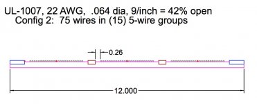
You could use 22AWG UL-1007 wires in Config 2 with (15) 5-wire groups, and retain the 12" panel width.
Most drawing features could remain the same except the stator lattice slot depths would have to be adjusted for .064 diameter wire, and the pin locations on the stretching jig would have to be changed from 90 wires to 75 wires. Also; 5-wire groups would not return a sixth wire to the bottom of the jig-- so you would have to clip some wires at the top of the stator. Not as easy but still do-able.
Attachments
Here's another option:
You could use 22AWG UL-1007 wires in Config 2 with (15) 5-wire groups, and retain the 12" panel width.
Most drawing features could remain the same except the stator lattice slot depths would have to be adjusted for .064 diameter wire, and the pin locations on the stretching jig would have to be changed from 90 wires to 75 wires. Also; 5-wire groups would not return a sixth wire to the bottom of the jig-- so you would have to clip some wires at the top of the stator. Not as easy but still do-able.
Hi @CharlieM,
Is there anything special about the 12" width for the electronically segmented stators ? I read that you chose the segmented width (and cross-member height) to fit your pre-existing [beam slitter] frames. If you didn't already have pre-existing frames, would you have selected a different [wider] width ?
The 24.4" width of the Mylar C stock on the tensioning jig is a upper physical size constraint (considering wrapping the sides of the jig). More than 90 wires on the wire stretching jig is another constraint to contend with as well as the inner-tube diameter. I read another build thread that used an 18.5" width, but he had tearing difficulties with that width on the tensioning jig and the thread ran its course with no final published results.
The spreadsheet models adding 2 wires to each of the 15 x 6-wire groups (15 x 8-wire groups, total of 120 wires) will yield @ a 3-4dB increase in sensitivity, but I don't know if it would adversely affect other things such as imaging, off axis response, cross member stability, gap bottoming out, distortion, etc. This would still be narrower than the 18.5" build (2.73" wider baffle than stock, each of the 3 vertical sections would be 0.91" wider than stock).
Thanks much
We've all heard how inefficient ESLs are supposed to be, so when designing my very first ESL, I agonized over the panel dimensions, out of fear I would spend a ton of money and time and end up with a speaker that wouldn't play loud enough. I believe it was fellow member "Few" who told me not to worry about it, and he was right. My first speakers' 12 x 48 panels played plenty loud.
And when later upgrading to the wire panels, the 12" width worked out about right. My panels are already wider and taller than most commercial hybrid ESLs, and they can play to painful volume, so I saw no reason to make them larger in my latest speaker builds.
Sanders' ESL is a bit wider to offset the extra height of the TL bass box, but area-wise, it's not larger. Most commercial hybrids are proportionally about the same for a reason-- they've all learned over the years what works performance-wise and aesthetically, and there's no compelling reason to use a larger panel in a hybrid speaker. This is my view also.
If you want to increase the panel width as you described; dispersion would not suffer in the far field because it would be segmented accordingly. In a small room with forced near-field listening, dispersion/imaging would be perceived as less wide/less precise.
The span between diaphragm supports would still fall within the 100*d/s max rule, so no problem there. And the height of the wooden wire support slats could remain the same.
You had mentioned in an earlier communication that you might also increase the panel height. At some point, increasing area/capacitance would become prohibitive for the amp. The segmentation resistors would mitigate that, but I don't now how to calculate it or define a practical limit. Perhaps one of the more knowledgable members here can advise you on that.
Good luck with your project!
Last edited:
We've all heard how inefficient ESLs are supposed to be, so when designing my very first ESL, I agonized over the panel dimensions, out of fear I would spend a ton of money and time and end up with a speaker that wouldn't play loud enough. I believe it was fellow member "Few" who told me not to worry about it, and he was right. My first speakers' 12 x 48 panels played plenty loud.
And when later upgrading to the wire panels, the 12" width worked out about right. My panels are already wider and taller than most commercial hybrid ESLs, and they can play to painful volume, so I saw no reason to make them larger in my latest speaker builds.
Sanders' ESL is a bit wider to offset the extra height of the TL bass box, but area-wise, it's not larger. Most commercial hybrids are proportionally about the same for a reason-- they've all learned over the years what works performance-wise and aesthetically, and there's no compelling reason to use a larger panel in a hybrid speaker. This is my view also.
If you want to increase the panel width as you described; dispersion would not suffer in the far field because it would be segmented accordingly. In a small room with forced near-field listening, dispersion/imaging would be perceived as less wide/less precise.
The span between diaphragm supports would still fall within the 100*d/s max rule, so no problem there. And the height of the wooden wire support slats could remain the same.
You had mentioned in an earlier communication that you might also increase the panel height. At some point, increasing area/capacitance would become prohibitive for the amp. The segmentation resistors would mitigate that, but I don't now how to calculate it or define a practical limit. Perhaps one of the more knowledgable members here can advise you on that.
Good luck with your project!
Thanks much. I did not know about the "100*d/s max rule" (if I read it before, it didn't sink in until now) and never thought about using an odd number of wires with a return wire from the top (Magnepan does that with their ribbon tweeters). Both helpful information.
I did see the resistor values drop when modeling a taller panel, but no SPL increases. Width and height both increase total surface area, so I don't understand why height does not contribute to SPL unless it is not modeled in the spreadsheet.
FWIW, the comb spacing/indexing jig is working well on test pieces so it is getting time to finalize on a design before ordering and cutting materials. If possible, I would like similar efficiencies for the both the (mid/tweet) stator panels and planar bass panels (should I choose to use them).
Also read up on the voltage multiplier circuit following the stepup transformer last night in the attempt to further understand what is going on.
I forgot you weren't in the US. I bought some UL-1061 at a great price from China but I had to buy 3,050 meters of it.
3,050 meters isn't too bad. The one i found was 6,100 meters. Do you mind sharing your source for the 3,050 meters?
Hey Charlie,
I thought I might continue on our conversation here instead of e-mails so we can benefit everyone. I went through your e-mail and you told me the stators and the diaphragm are essentially like capacitors. I think I roughly understand, but I would love to get some clarity on wiring these guys up if it's possible?
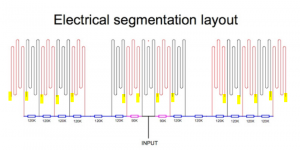
Looking at the electrical segmentation picture (attached, first picture) I still don't really understand where does the other end of the wire gets connected to (those highlighted in yellow). If i understand correctly, they should make a complete circuit and hence be connected to the diaphragm am I right?
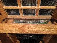
Looking at the second picture instead, it seems to me they are connected to the perfboard instead? Would probably help if there are some pictures and markings on the underside of the perfboard. If it's too troublesome, does that mean the other end of wire (where there is no resistor) is just soldered to any of the tabs on the perfboard and they'll still be able to make a complete circuit with the diaphragm over there? 😕
I thought I might continue on our conversation here instead of e-mails so we can benefit everyone. I went through your e-mail and you told me the stators and the diaphragm are essentially like capacitors. I think I roughly understand, but I would love to get some clarity on wiring these guys up if it's possible?
Looking at the electrical segmentation picture (attached, first picture) I still don't really understand where does the other end of the wire gets connected to (those highlighted in yellow). If i understand correctly, they should make a complete circuit and hence be connected to the diaphragm am I right?
Looking at the second picture instead, it seems to me they are connected to the perfboard instead? Would probably help if there are some pictures and markings on the underside of the perfboard. If it's too troublesome, does that mean the other end of wire (where there is no resistor) is just soldered to any of the tabs on the perfboard and they'll still be able to make a complete circuit with the diaphragm over there? 😕
Attachments
- Home
- Loudspeakers
- Planars & Exotics
- Wire for wire-stator ESL