Hey Charlie,
I thought I might continue on our conversation here instead of e-mails so we can benefit everyone. I went through your e-mail and you told me the stators and the diaphragm are essentially like capacitors. I think I roughly understand, but I would love to get some clarity on wiring these guys up if it's possible?
Looking at the electrical segmentation picture (attached, first picture) I still don't really understand where does the other end of the wire gets connected to (those highlighted in yellow). If i understand correctly, they should make a complete circuit and hence be connected to the diaphragm am I right?
Looking at the second picture instead, it seems to me they are connected to the perfboard instead? Would probably help if there are some pictures and markings on the underside of the perfboard. If it's too troublesome, does that mean the other end of wire (where there is no resistor) is just soldered to any of the tabs on the perfboard and they'll still be able to make a complete circuit with the diaphragm over there? 😕
I attended a redneck high school in Georgia and nothing more so my answers to your questions may not be entirely correct, but here's how I see it:
The sketch you posted from my website is both correct and accurate. The wire ends highlighted in yellow are clipped off at the panel edges-- they do not extend further or connect to anything else. I may not fully understand it but I know it works.
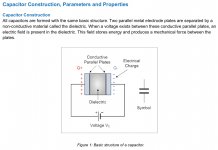
I've compared the panel to a capacitor; with the stators being the plates and the the air gap the insulator/dielectric.
My sketch of the wire layout looks like an open/incomplete circuit because it only shows one plate of the capacitor. A complete capacitor circuit is shown below. Note that there is only a single lead (not two) connecting to each plate, and it takes both plates and the gap between them to complete the circuit:
https://www.diyaudio.com/forums/attachment.php?attachmentid=850253&stc=1&d=1591397676
The ESL capacitor is more complicated because there's a charged diaphragm inserted in the air gap. I see the two stators and diaphragm collectively as two capacitors sharing a common center plate.
Looking at the full schematic below; I see the diaphragm lead grounding thru the bias supply to the transformer secondaries, as completing the capacitor circuits, and the resulting charges on the plates driving the diaphragm, with each polarity swing of the sine-wave (music analog) powering the transformers.
If anyone can either affirm or correct any of the above, please do-- I would appreciate it.
https://www.diyaudio.com/forums/attachment.php?attachmentid=850267&stc=1&d=1591400257
Attachments

Last edited:
3,050 meters isn't too bad. The one i found was 6,100 meters. Do you mind sharing your source for the 3,050 meters?
Yes, I registered at Alibaba, requested a quote and several companies responded. I purchased the wire from Zhejiang Jiahui Wire And Cable Co., Ltd.
The sales person as Alan Pei
3,050 meters 20AWG UL-1061 single strand, black $359 with shipping.
The wire was beautiful-- the i.d. lines printed on the insulation (required by law) were so small as to be unnoticeable, so did not detract from the aesthetics of the finished speaker.
Last edited:
The wire ends highlighted in yellow are clipped off at the panel edges-- they do not extend further or connect to anything else.
Ahhh awesome! Thanks! I have a better grasp at understanding the build now.
Yes, I registered at Alibaba, requested a quote and several companies responded. I purchased the wire from Zhejiang Jiahui Wire And Cable Co., Ltd.
The sales person as Alan Pei
3,050 meters 20AWG UL-1061 single strand, black $359 with shipping.
The wire was beautiful-- the i.d. lines printed on the insulation (required by law) were so small as to be unnoticeable, so did not detract from the aesthetics of the finished speaker.
Alright! Thanks Charlie! Just messaged them.
On a side note, how does one go about choosing a suitable woofer to replace the peerless? I think ScanSpeak speakers may be more accessible for me as they have a distributor here in Malaysia.
On a side note, how does one go about choosing a suitable woofer to replace the peerless? I think ScanSpeak speakers may be more accessible for me as they have a distributor here in Malaysia.
I think we would not find universal agreement on any answer to that question because there is no ideal woofer for this application. One can only choose among compromises that best fit the goal. Here's my take on it:
The first consideration was matching the ESL and woofer "Q"s. The best we can do here is avoid an excessive mismatch.
Woofer Q is basically a measure of how it stores and releases the energy. There is a mechanical component (Qms) associated with the stiffness/looseness of the cone's suspension + mass/inertia, and also an electrical component (Qes) associated with the voice coil inductance (number of turns in the winding), which creates a force (back-emf) that opposes the drive signal. Finally; there is the total Q (Qts) which is derived by a formula that combines the Qms and Qes.
ESL Q: A 6-micron diaphragm has ultra-low mass, hence correspondingly low inertia, and is accordingly exceptionally well dampened by the much heavier air mass it's coupled to. Basically; a 6-micron diaphragm can start & stop on a dime without ringing. An ESL is about as close to zero Q as one can get-- only a plasma driver has lower Q.
One might reasonably believe the cone's mass/inertia would be the predominant restraint on acceleration, but tests show in most cases it's the voice coil inductance/back-emf opposing the drive signal. I choose a woofer with not more than 1mH inductance; preferably with a strong magnet to bring the efficiency back up (lower inductance usually means less drive power; although high end woofers generally have good drive power and employ shorting rings to reduce the inductance).
So; a Q-matched woofer would have low inductance, low Qts, and low moving mass would be icing on the cake. I would prioritize the parameters in that order. But then, these considerations are modified by the choice of enclosure (sealed, ported, transmission line, or open baffle).
Since we were discussing my design, I will refer to my home speakers which have the woofer below the panel in a tapered H open baffle. Typically, an open baffle application requires long excursion to offset the dipole roll off, so a high Q woofer with floppy suspension would be used normally.
However; the ideal OB woofer would not be able to track in sync with the much lower Q ESL. So here a compromise must be made. One could split the difference with a medium Q woofer (lets say about 0.5 Qts). Or choose a lower Qts woofer and apply a ton of EQ on the bottom end.
It helps in my H-baffle EQ that I chop off the signal to the woofers and cross in a pair of subs crossing at 60Hz using a steep filter slope. I can then choose a medium Q woofer (0.5 ish) and use little or no EQ on the bottom end, or a lower Q woofer (let's say 0.35) and apply some (but not excessive) EQ to bring the mid bass down to meet the subs.
I chose the Peerless SLS, which is a medium Q woofer with good excursion that still works well in an OB, and an exceptional value at its price point. I haven't tried them without the subs but others have and say it works well. With the subs unloading the bottom end, my speakers can REALLY ROCK.
If you want to use a similar woofer; choose one with similar Qts and voice coil inductance, and if possible, same or better X-max (excursion).
Jazz
Last edited:
Wow thanks! That was extremely helpful!
Just for further understanding, does that mean the relationship between QTS and excursion is directly related? I.e higher qts will normally more excursion?
Just for further understanding, does that mean the relationship between QTS and excursion is directly related? I.e higher qts will normally more excursion?
Wow thanks! That was extremely helpful!
Just for further understanding, does that mean the relationship between QTS and excursion is directly related? I.e higher qts will normally more excursion?
Not necessarily but I think in most cases, yes, since a high Q woofer would be rather floppy and therefore would need to handle long excursions, lest damage occur.
The practical limit is approached when the panel capacitance increases enough to start pushing the resonance frequency with transformer leakage inductance below 20kHz. This resonance defines the HF limit as a 2nd order LP filter, rolling off at 12dB/oct above that. More details on the concept here:…You had mentioned in an earlier communication that you might also increase the panel height. At some point, increasing area/capacitance would become prohibitive for the amp. The segmentation resistors would mitigate that, but I don't now how to calculate it or define a practical limit.
Segmented Wire Stator ESL simulator (esl_seg_ui)
You can calculate the resonance frequency by hand:
Fres = 1 / ( 2*Pi*sqrt(L*C) )
Use one of many online calculators…
Series LC Circuit Impedance Calculator • Electrical, RF and Electronics Calculators • Online Unit Converters
Or the ESL transformer spreadsheet posted here:
ESL electronics 101 for the electronics challenged
For hybrid ESLs that are segmented like yours and driven with low leakage toroidal transformers, in general the limit is not reached before the height of your ceiling is.
The practical limit is approached when the panel capacitance increases enough to start pushing the resonance frequency with transformer leakage inductance below 20kHz. This resonance defines the HF limit as a 2nd order LP filter, rolling off at 12dB/oct above that. More details on the concept here:
Segmented Wire Stator ESL simulator (esl_seg_ui)
You can calculate the resonance frequency by hand:
Fres = 1 / ( 2*Pi*sqrt(L*C) )
Use one of many online calculators…
Series LC Circuit Impedance Calculator • Electrical, RF and Electronics Calculators • Online Unit Converters
Or the ESL transformer spreadsheet posted here:
ESL electronics 101 for the electronics challenged
For hybrid ESLs that are segmented like yours and driven with low leakage toroidal transformers, in general the limit is not reached before the height of your ceiling is.
This is why I post on this forum

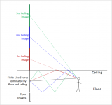
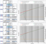
For theoretical line-sources, the assumption is that that ESL is infinitely long, or at least floor to ceiling in height where the acoustic mirrors will effectively extend the height. For theoretical line sources, SPL does not increase when adding height. But, as mentioned on the directions TAB, the spreadsheet does provide the ability to estimate the response if the line-source is finite in length, rather than theoretically infinite. The option is selected by input parameter 10==>. With “Finite” selected, you will find that the LF SPL starts sloping off at -6dB/oct below some transition frequency which is a function of source height and listening distance. Two attached pics illustrate movement of transition frequency with change in height, or change in listening distance using an unsegmented panel to improve clarity of the trends.…I did see the resistor values drop when modeling a taller panel, but no SPL increases. Width and height both increase total surface area, so I don't understand why height does not contribute to SPL unless it is not modeled in the spreadsheet...
The formula for determining near/far field transition relative to a panel dimension is:
F = c * r / d^2
where:
c = speed of sound
r = listening distance
d = panel dimension
A separate spreadsheet for playing with the breakpoints of a line source was posted here:
Segmented Wire Stator ESL simulator (esl_seg_ui)
An example comparison with measurements shows theory provides good guidance for design.
First ESL build - Full Range .
Depending what your listening distance will be, you may find that adding height to the ESL only adds additional output for frequencies below your intended crossover point.(ie nothing to be gained from SPL standpoint). Extending the height of your ESL may provide other benefits you desire though, like more uniform HF response when standing or laying on the floor.
Attachments

Last edited:
... The wire ends highlighted in yellow are clipped off at the panel edges-- they do not extend further or connect to anything else. I may not fully understand it but I know it works.
...
That is a question I had as well plus why are 14 of the 15 coils all attached on 1 end and the center coil is attached on both ends.
Should the center coil also be clipped short on 1 side ???
I did find the following picture on the web and wondered why the wires were clipped so short (too short for soldering) which now has been answered.

The "air capacitor" analogy is helpful in bettering my understanding of the system as a whole.
On another web build, I saw that the circuit had a drain to ground (10M). Is there a reason why your circuit does not have a drain ?
Schematics | Steen Frank Jensen

TIA
Last edited:
...
For hybrid ESLs that are segmented like yours and driven with low leakage toroidal transformers, in general the limit is not reached before the height of your ceiling is.
Thank you very much.
[UPDATE] Didn't see your last post regarding height.
...
Depending what your listening distance will be, you may find that adding height to the ESL only adds additional output for frequencies below your intended crossover point.(ie nothing to be gained from SPL standpoint). Extending the height of your ESL may provide other benefits you desire though, like more uniform HF response when standing or laying on the floor.
Thank you for the explanation. I noticed the 3 settings of "==> 10" made a difference on SPL, but didn't understand why it wasn't linear like adding more width. As for other reasons, thank you for that. I currently have planers with 60" tall ribbons and the soundstage is the same sitting or standing.
Last edited:
That old pic brings back some memories (really sloppy job I did on that one).
Regarding the connections between the resistors and wire coils; it makes no difference whether one or both ends (including the center coil) connect to the resistors. It's just convenient and makes routing the wires less "busy" if just one wire end from each coil connects to the resistors.
Regarding the ground/center tap in Frank Jensen's schematic. It's certainly interesting and there are more connections there than the one you mentioned-- even to both sides of the bias supply (thru additional resisotors). Frank's a pretty smart fellow so his layout may give some advantage-- I can't say.
I can affirm that my schematic accurately reflects the connections in my speaker, that I've built probably ten pairs of speakers using the same layout, and none have failed or tripped a protection circuit in my amps.
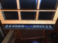
The resistor/stator connections are a bit neater in my new speakers:
https://www.diyaudio.com/forums/attachment.php?attachmentid=850817&stc=1&d=1591554460
https://www.diyaudio.com/forums/attachment.php?attachmentid=850818&stc=1&d=1591554460
https://www.diyaudio.com/forums/attachment.php?attachmentid=850817&stc=1&d=1591554460
https://www.diyaudio.com/forums/attachment.php?attachmentid=850818&stc=1&d=1591554460
Attachments

That old pic brings back some memories (really sloppy job I did on that one). ....
Your posted images add clarity to newbies. That picture depicted a helpful important overlooked detail. My primary goal is understanding and functionality first and foremost, cosmetics are a concern somewhere further down the line along with audiophile jewelry. 🙂
The "air capacitor" concept brought up more questions. Is there an optimal way of connecting the 2 "plates" ?
When I have seen capacitors rolled, the supply leads are usually on apposing ends of the plates (assuming to distribute the charge more evenly across the entire span) as depicted in the following rendering.
Rolled caps have one lead in the center of the roll (on one side of one plate) and the other lead is on the outside of the roll (on the far side of the other plate).
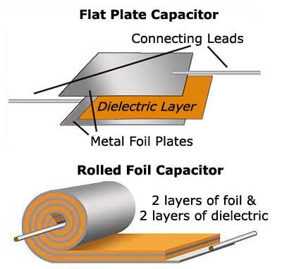
Is there advantage to be had with the stats doing something similar to span the height of the stat "plates" ?
e.g.
- A) Wire one stator on the bottom and the other on the top.
- B) Wire one stator coil on the left and the other on the right if only using 1 attachment point.
TIA
Last edited:
- Home
- Loudspeakers
- Planars & Exotics
- Wire for wire-stator ESL