I have a question about the right way to start up this amplifier. My dad had built it originally with a U52 rectifier valve with a directly heated cathode. There was a DPDT toggle switch on the HT line out of the power supply chassis, but the wiring was broken and cut and it wasn't clear whether the switch was there to cut the HT supply or whether it was for a high voltage tap off to an electrostatic tweeter he once used.
We've updated the power supply to the "new" 1949 version, so the rectifier valve is now a 5V4, with an indirectly heated cathode. As I understand it, the longer delay from this heater warming up the cathode will allow the 20uF capacitor to gradually charge up as the rectifier starts conducting, so that sounds like a good thing. But if the PS reaches full DC voltage before the amplifier output valves have warmed up then the PS sits there with no load so the voltage will reach the full 635V we measured, yet the capacitor is only rated at 600V. Should I be concerned about this momentary over-voltage?
One alternative scheme would be to switch the DC before the capacitor, then on switch-on wait for the amplifier valves to fully warm up before closing this switch. The PS would then see a load and the DC voltage won't get anywhere the 600V rating of the capacitor. But connecting the uncharged capacitors to the pre-warmed PS would draw a large current through the rectifier valve, which I have read is not a good thing.
How should I manage the switch-on with the components we have in this build? What's worse, the momentary over-voltage on the first cap, or the large current spike through the rectifier if it gets connected to discharged capacitors? There is the one 20uF cap and 4 more 10uF ones in the amplifier, the last two having dropping resistors to the HT supply.
Thanks,
Graham.
Oldvinylplayer,
In looking at the photos, it appears that there is no power supply bleeder resistor on the output filter capacitor. If this is the case, there is virtually no load on the power supply when it is powered on and not connected to a functioning amplifier. I am also guessing that the 635vdc no load voltage you saw when you did the quick test was higher than one might expect due to the age of the power transformer. I am thinking it may have been originally designed for 115vac primary voltage and today we see more like approx. 122vac or about 6% high. Thus, I am not surprised by the 635vdc you measured. I would install a bleeder resistor that dropped 6 milliamps or so. Keep in mind the resistor will need to dissipate just over 4 watts, so it should be a 12 watt minimum size and mounted where it can radiate some waste heat. The bleeder will help to hold down the HV a little if the power supply is turned on without the amplifier and discharge the power supply once its turned off. Good luck with your project! Mickeystan
In looking at the photos, it appears that there is no power supply bleeder resistor on the output filter capacitor. If this is the case, there is virtually no load on the power supply when it is powered on and not connected to a functioning amplifier. I am also guessing that the 635vdc no load voltage you saw when you did the quick test was higher than one might expect due to the age of the power transformer. I am thinking it may have been originally designed for 115vac primary voltage and today we see more like approx. 122vac or about 6% high. Thus, I am not surprised by the 635vdc you measured. I would install a bleeder resistor that dropped 6 milliamps or so. Keep in mind the resistor will need to dissipate just over 4 watts, so it should be a 12 watt minimum size and mounted where it can radiate some waste heat. The bleeder will help to hold down the HV a little if the power supply is turned on without the amplifier and discharge the power supply once its turned off. Good luck with your project! Mickeystan
Thanks Mickeystan.
We're in Australia, and the mains at my place typically measures 250V. The transformer has 220V, 240V, and 260V primary taps. I used the 240V tap because that's the one that was used originally. The open circuit voltage on the transformer was 475-0-475 VAC, so quite a bit higher than the rated 425-0-425. 475VACx1.4=665VDC, so I think it all adds up.
You've alerted me to an interesting issue though. I'll need to see what the on-load DC voltage is, and possibly use a different primary tap. The transformer is only rated at 125mA, verses the 150mA Williamson spec., so I do expect more than a little voltage sag on-load. We'll see how it looks when connected to the amplifier and producing some power.
I like your suggestion of a bleeder resistor, I'll do that to bring the no-load voltage down a bit, and it will also be good for safety. That 20uF 600V cap took a good 15 mins to discharge with no load. Finding space for the resistor will be a challenge, but I guess it could also go in the amplifier.
Thanks for your help.
Graham.
Oldvinylplayer, Sorry, I did not pick up on the fact that you are located in Australia. Since the transformer has a 260vac input option, you can take advantage of that once you get everything going if you find the B+ is too high. With your umbilical connection of high voltage between the power supply and amplifier chassis, you could split the bleeder into two bleeders one in the power supply and one in the amplifier chassis since you will have some additional decoupling electrolytic capacitors in it as well. Thus, both bleeders could be a bit smaller in wattage. Maybe bleed 4 milliamps in one chassis and another 3 milliamps in the other. Just food for thought since you have limited space in the power supply chassis. This way, the power supply would not be void of its own bleeder if run un- connected to the amplifier.
Best Regards, Mickeystan
Best Regards, Mickeystan
Good idea. I'll do one in each chassis. After looking at the schematic I've realised that the bleeder resistor for the PS can connect from one of the 5V transformer terminals to earth, and there is plenty of space and a convenient screw for an earth terminal in that area.
Thanks again for the suggestion,
Graham.
Thanks again for the suggestion,
Graham.
Safety does dictate the use of bleeders. Sometimes those are inherent when using series connected caps.
I'd check the loaded heater voltage, and change the mains pri tap to get closest to 6.3V. also worth checking how much your mains varies over the day.
I'd check the loaded heater voltage, and change the mains pri tap to get closest to 6.3V. also worth checking how much your mains varies over the day.
OK, yes I've read that keeping close to 6.3V is important for valve longevity, but how important is keeping close to the 450VDC rail?
Graham.
Graham.
Heater voltage can only easily be modified by PT prim tap. Power dissipation is controlled by bias. B+ certainly needs to be then checked, but should be within acceptable range if the PT has OK voltage spec.
Phase of feedback signal?
More progress today. We've almost completed the wiring in the amplifier chassis, and hoping to fire it up tomorrow.
But I have a question. How do you determine which side of the output transformer secondary winding to connect the feedback resistor to? We can probably reverse engineer from photos which side it was on originally, but I'm curious to learn if there is a method for working this out?
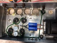
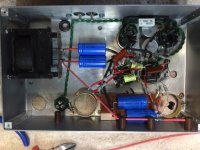
Here's some photos of the progress, as always, comments on the wiring layout are welcome. We've taken some liberties with the earthing.
Graham.
More progress today. We've almost completed the wiring in the amplifier chassis, and hoping to fire it up tomorrow.
But I have a question. How do you determine which side of the output transformer secondary winding to connect the feedback resistor to? We can probably reverse engineer from photos which side it was on originally, but I'm curious to learn if there is a method for working this out?
Here's some photos of the progress, as always, comments on the wiring layout are welcome. We've taken some liberties with the earthing.
Graham.
Attachments
But I have a question. How do you determine which side of the output transformer secondary winding to connect the feedback resistor to?
What secondary impedance taps are provided on that transformer?
The transformer has two output leads, these are the ones we need to work out the correct phase for. On top of the transformer are multiple taps, which have jumpers to be soldered on to match the speaker impedance to be used. You can see this in the photos in post #11 above.
The secondary winding comes out on two wires below, which are both covered in ancient white cotton, ie. no markings. It's the phase of these that I think matters.
Any ideas?
Graham.
The secondary winding comes out on two wires below, which are both covered in ancient white cotton, ie. no markings. It's the phase of these that I think matters.
Any ideas?
Graham.
Aha, well that actually simplifies things. You can do one of two things:
1. Apply a sine wave to the primary, then look at the secondary and see what the polarity is.
2. Flip a coin, connect the feedback to one side, connect the other to signal common, and if the amp oscillates when you turn it on, turn it off and reverse the connections.
Since I'm lazy, I use Method 2.😀
OK, so that was our first thought, but is it safe to power it up with positive feedback?
What do people use for a dummy load for such tests, and if it's a resistor how do you know if anything's amiss? I definitely don't want to use the 1952 Bakers Selhurst speaker.
Graham.
What do people use for a dummy load for such tests, and if it's a resistor how do you know if anything's amiss? I definitely don't want to use the 1952 Bakers Selhurst speaker.
Graham.
You absolutely want a dummy load. Any 8-20 ohm power resistor will do. A few seconds of oscillation won't hurt anything.
Your scope (or an AC voltmeter) will tell you. The amp and dummy load might even make physical noise. I *always* have a scope on the output of any new build when I first power it up. That would go double for a Williamson.
Graham, if you connect the feedback lead with its series resistor (not sure what value your amp has but it is likely around 4k7) through another series resistor of about 47k, then you only start the amp with a little bit of feedback, and hence your apprehension can somewhat allayed if the output signal increases rather than decreases.
Success!
It's running!
To address the rather high no-load voltage issue we changed the PS transformer primary to the 260V tap. This gave 432-0-432 VAC and 595VDC no-load, so just under the 600V rating of the first capacitor. I still plan to add bleeder resistors which will hopefully drop this a bit further.
After reading all the advice here, we decided to flip a coin and choose one side of the output transformer for the feedback resistor and just fire it up. It turns out we chose the correct side and the amp started up and appeared stable.
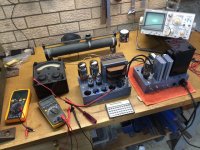
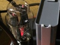
There's a picture of the test set up below, which follows Williamson's recommendation to insert a mA meter between the supply and the output transformer primary tap and adjust for 125mA. We used a dummy load on the output and also had a cheap loudspeaker connected in parallel (with its own series resistor) so we could hear what was going on. It started up dead silent, no oscillating, and no audible hum except when the input line was touched with a test wire to simulate an audio input signal and therefore test the whole signal chain.
One very interesting finding was that after a couple of power cycles, the 5V4 rectifier started arcing over internally creating a spectacular purple light show with a consequent dip in the supply voltage. After pondering this for a while, we decided to check the valve data book, only to find that the 5V4 is rated for just 375-0-375 V RMS on the input. We have 432-0-432, not hugely over, but possibly enough to explain the arcing? The 5V4 is what Williamson recommends for the rectifier in the 1949 update, and it's a mystery to me why he should do this when the transformer is specced at 425-0-425.
Luckily one of the two surviving valves from the original amplifier was the U52 directly heated cathode rectifier. The U52 is rated for 500-0-500VAC. We fitted this 60 year old valve, fired the power supply up, and everything settled down with no arcing and a stable supply voltage.
After soaking for an hour or so (that's the amp, not us) we got up the courage to connect my laptop as a source, and the original 1950s Bakers speaker to the output. With this relatively high efficiency speaker the amp is completely hum free and sounds fantastic! Needles to say, my dad was absolutely thrilled to be hearing the amp and speaker again after probably 40 years.
We did some quick frequency sweeps with the CRO connected on the output and got nice looking sine waves, the frequency response looks sensible, and it really does sound great on music. I've been listening to it for a few evenings now and I can't fault it. On a big speaker, 15 Watts can produce quite a volume!
Still to do:
Make a solid earth connection between the two chassis.
Add the bleeder resistors.
Balance the bias of the KT66 output valves.
Listen to music some more.
Fill in the holes on the amp chassis with dummy can capacitors.
More measurements of distortion, power output and frequency response.
Mount both chassis on a timber base, with air vents underneath.
Listen to lots of music.
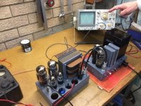
Here's some pictures of the amp being tested.
Graham, and a very happy father.
It's running!
To address the rather high no-load voltage issue we changed the PS transformer primary to the 260V tap. This gave 432-0-432 VAC and 595VDC no-load, so just under the 600V rating of the first capacitor. I still plan to add bleeder resistors which will hopefully drop this a bit further.
After reading all the advice here, we decided to flip a coin and choose one side of the output transformer for the feedback resistor and just fire it up. It turns out we chose the correct side and the amp started up and appeared stable.
There's a picture of the test set up below, which follows Williamson's recommendation to insert a mA meter between the supply and the output transformer primary tap and adjust for 125mA. We used a dummy load on the output and also had a cheap loudspeaker connected in parallel (with its own series resistor) so we could hear what was going on. It started up dead silent, no oscillating, and no audible hum except when the input line was touched with a test wire to simulate an audio input signal and therefore test the whole signal chain.
One very interesting finding was that after a couple of power cycles, the 5V4 rectifier started arcing over internally creating a spectacular purple light show with a consequent dip in the supply voltage. After pondering this for a while, we decided to check the valve data book, only to find that the 5V4 is rated for just 375-0-375 V RMS on the input. We have 432-0-432, not hugely over, but possibly enough to explain the arcing? The 5V4 is what Williamson recommends for the rectifier in the 1949 update, and it's a mystery to me why he should do this when the transformer is specced at 425-0-425.
Luckily one of the two surviving valves from the original amplifier was the U52 directly heated cathode rectifier. The U52 is rated for 500-0-500VAC. We fitted this 60 year old valve, fired the power supply up, and everything settled down with no arcing and a stable supply voltage.
After soaking for an hour or so (that's the amp, not us) we got up the courage to connect my laptop as a source, and the original 1950s Bakers speaker to the output. With this relatively high efficiency speaker the amp is completely hum free and sounds fantastic! Needles to say, my dad was absolutely thrilled to be hearing the amp and speaker again after probably 40 years.
We did some quick frequency sweeps with the CRO connected on the output and got nice looking sine waves, the frequency response looks sensible, and it really does sound great on music. I've been listening to it for a few evenings now and I can't fault it. On a big speaker, 15 Watts can produce quite a volume!
Still to do:
Make a solid earth connection between the two chassis.
Add the bleeder resistors.
Balance the bias of the KT66 output valves.
Listen to music some more.
Fill in the holes on the amp chassis with dummy can capacitors.
More measurements of distortion, power output and frequency response.
Mount both chassis on a timber base, with air vents underneath.
Listen to lots of music.
Here's some pictures of the amp being tested.
Graham, and a very happy father.
Attachments
Oldvinylplayer, Great job in restoring your father's amplifier! It must have been a wonderful letting Dad hear it again playing music. Glad to hear you still had a working U52 rectifier tube. The one thing you did that just never works for me (when I just guess) is getting the feedback polarity right the first time around. Great project and I have enjoyed following it.
Mickeystan
Mickeystan
- Status
- Not open for further replies.
- Home
- Amplifiers
- Tubes / Valves
- Williamson amplifier re-build