Thanks guys, it's been a lot of fun for us to do this together. We've got a bit more to do, and I'll post better photos when it's properly finished. And I'm sure there will be more questions to ask as we tidy it all up.
We're also starting to think about a suitable pre-amplifier with tone controls (mono), any suggestions?
Graham.
We're also starting to think about a suitable pre-amplifier with tone controls (mono), any suggestions?
Graham.
One very interesting finding was that after a couple of power cycles, the 5V4 rectifier started arcing over internally creating a spectacular purple light show with a consequent dip in the supply voltage. After pondering this for a while, we decided to check the valve data book, only to find that the 5V4 is rated for just 375-0-375 V RMS on the input. We have 432-0-432, not hugely over, but possibly enough to explain the arcing? The 5V4 is what Williamson recommends for the rectifier in the 1949 update, and it's a mystery to me why he should do this when the transformer is specced at 425-0-425.
Perhaps this is another situation where the series SS diode tweak might help. The tweak originates in the need to contain the "fireworks" that can occur, when current production 5AR4/GZ34s are employed.
FWIW, I suggest UF4007s instead of the 1N4007s shown in the uploaded graphic. The idea is that less noise, from the outset, has to be better, even though the vacuum rectifier blocks SS diode switching noise.
Another thing to watch out for when using 5V4/GZ32s near the PIV limit is strict adherence to the published 1st filter cap. size limit.
Attachments
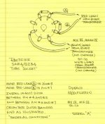
In addition to Eli's advise, the high secondary voltage requires two 1N4007 or UF4007 in series with each anode, as the PIV would exceed the rating of just one ss diode.
As you note, the 'original' Williamson circuit used a Marconi U52 (as befitted a Marconi sponsored design) with its 500VAC design rating.
Some 5V4 datasheets show a 375VAC design centre max rating, whereas the Sylvania datasheet shows design curves for 400VAC. I guess the commonly available 5V4, with its 2A heater current requirement, and the typical use of 'new' stock, would have been the better compromise for WW DIYers at the time. Plus the slower voltage rise time of an indirectly heated 5V4 cathode would have reduced over-voltage stress on electrolytic caps.
Last edited:
Thanks Eli and Tim,
I just ran the SS diode idea past my father, and he says "not in my amplifier", so I guess that's not an option.
Tim, yes the original 1947 Williamson schematic specified the U52, and that is how this amp was built originally, which is why we had the old U52 to hand. Are you implying that 5V4s would have been OK in the day because they were more robust in some way? The valve we used here, the one that arced, is labeled 5V4G and was sold to us as NOS in an old looking Super Radiotron AWV box (probably not the original box).
Eli, the listings for 5V4s in our 1965 Wireless World Valve Data book all show 32uF maximum reservoir capacitance, so our 20uF should be OK? The max capacitance is blank for all the 5V4G listings.
I think we'll just stick with the U52, but thanks for your useful comments - we're learning (and re-learning) heaps as we go along.
Graham.
Eli, the listings for 5V4s in our 1965 Wireless World Valve Data book all show 32uF maximum reservoir capacitance, so our 20uF should be OK? The max capacitance is blank for all the 5V4G listings.
The GE datasheet I linked gave 10 μF. as "typical". Given that you are at or slightly over the published PIV limit, I'd go no higher than 15 uF. at the PSU filter's I/P and perhaps go with a 10 μF. metalized polypropylene film part in that 1st position. Make up for that reduction by increasing the amount of capacitance in the reservoir position. Space should not be a problem, as modern caps. are much more volumetrically efficient than parts from "way back when".
A worthwhile source of information is "Radiotron Designers Handbook" by F Langford-Smith, say 4th edition, 1953. It contains a wealth of information, including Williamson ccts and a section about power supply design and ripple current (this is your problem with the rectifier). I purchased a copy about 1960 and built Mullard 5-20's which were turned into Williamsons using el34s. Anyway, suggest you derate your kt66s a bit to preserve them. Such valve cost an arm a leg these days. Good listening.Thanks Eli and Tim,
I just ran the SS diode idea past my father, and he says "not in my amplifier", so I guess that's not an option.
Tim, yes the original 1947 Williamson schematic specified the U52, and that is how this amp was built originally, which is why we had the old U52 to hand. Are you implying that 5V4s would have been OK in the day because they were more robust in some way? The valve we used here, the one that arced, is labeled 5V4G and was sold to us as NOS in an old looking Super Radiotron AWV box (probably not the original box).
Eli, the listings for 5V4s in our 1965 Wireless World Valve Data book all show 32uF maximum reservoir capacitance, so our 20uF should be OK? The max capacitance is blank for all the 5V4G listings.
I think we'll just stick with the U52, but thanks for your useful comments - we're learning (and re-learning) heaps as we go along.
Graham.
Graham,
The arcing in the diode valve is likely to be when the inverse voltage on the 'off' diode increases to a point where the vacuum insulation can't sustain the voltage. That inverse voltage peaks when the first filter capacitor has charged up, and the off diode has twice the PT secondary VAC(peak) across it. Electrode separation and stray gas in the vacuum determine when arcing initiates.
A NOS tube would not have been operated for decades, so there could be a higher than normal concentration of stray gas when initially using the valve. Stray gas in the vacuum typically occurs over time as the glass and metal parts out-gas and the seals leak. The left over getter material reacts with the gas molecules, and a balance occurs between out-gassing and getter soaking. Getter performance increases with temperature, but so does outgassing, although I understand that operating a valve would normally result in a reduction in stray gas density.
I can appreciate your father's view about silicon diodes, but it may be a good idea to suggest that some technical improvements have become available over the last 50-60 years and it is worthwhile utilising them when appropriate. So many better parts are now available, such as using modern IEC rated fuses, and low-noise high-voltage stable resistors and electrolytic capacitors and low-distortion reliable poly coupling caps. There are also surreptitious improvements that can make the amp more robust to allow another 50-60 years of service, such as series ss diodes with the valve diode, and a secondary side fuse on the HT, and not just relying on a pot wiper terminal. And then there are the safety related subtle changes like bleeder resistors, and accepted protective earthing practices. And connecting an oscilloscope or even spectrum analyser to confirm performance is second nature now, but almost implausible for a 1950's DIYer.
Last edited:
If the amp used a U52 a 5U4 wouldn't the 5V4 give too high a voltage?
5U4's are cheap and plenty around.
Phil
5U4's are cheap and plenty around.
Phil
Phil, the datasheet for U52 is significantly different to 5U4G, and doesn't provide a plate resistance level to compare to the 5V4, so the only information for comparison between U52 and 5V4 is that the B+ voltage and current draw doesn't change between the original and improved Williamson circuits - so there appears to be no substantial voltage drop difference between those two options.
Using a 5U4G alternative would drop the B+ level, as it has a higher voltage drop than the 5V4, and the heater supply needs another 1A of rating.
Using a 5U4G alternative would drop the B+ level, as it has a higher voltage drop than the 5V4, and the heater supply needs another 1A of rating.
Oldvinylplayer, one other rectifier tube that may work for you is a 5R4. It draws 2.0 amps filament current and will not overload the filament winding on the power transformer. It also has plenty of inverse break down rating. The 5R4 tube variants are a lot more available than replacement U52's. I could not find a lot of data on vdrop of U52 rectifiers to compare to the 5R4 but, I doubt it would make any significant difference anyway. Just some more food for thought.
Mickeystan
Mickeystan
Things to watch out when employing 5R4s are capacitance limit and a large forward drop. At the rated 250 mA. B+ draw, the forward drop in a 5R4 is a whopping 67 V.
Eli, whats the forward drop on a U52 at 250ma draw? I could not find very much data on a U52 rectifier in capacitor input service. That said, the KT66s are set for a idle dissipation of 125ma and playing music would not likely ever see a sustained 250ma drop. Thus, I cannot help but wonder how much additional drop a 5R4 would really show in the actual circuit. Any thoughts?
Mickeystan
Mickeystan
U52 appears to be similar to 5V4, so comparison of 5V4 drop to 5R4 or 5U4 drop is the only available comparison it seems.
Perhaps the OP can play "mix & match". IIRC, the power trafo here has multiple B+ voltage capability. Use the "tall" capability of the trafo to feed a "potato masher" 5R4. Use a 15 μF. metalized polypropylene film 1st filter capacitor.
Of the "common" vacuum rectifiers, only the 5AR4/GZ34 exhibits a smaller forward drop than the 5V4/GZ32.
Of the "common" vacuum rectifiers, only the 5AR4/GZ34 exhibits a smaller forward drop than the 5V4/GZ32.
Fantastic and most informative restore, Graham.
You guys are faaaaar ahead of my job. There's some more pics for you in the Pye thread.
Cheers
bulgin
You guys are faaaaar ahead of my job. There's some more pics for you in the Pye thread.
Cheers
bulgin
Thanks everyone for the advice and suggestions for the rectifier. The U52 is working well, so I think we'll stick with that for now. But thanks to your input, we have a few avenues to pursue if the U52 fails.
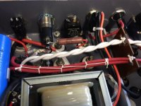
My work has been way too busy, so progress this past week has been slow, but we did get bleeder resistors added in the power supply chassis. We had a few 47K 2W resistors left over from the build, so we used two of those in series. This has dropped the B+ a little, but the caps now discharge in a reasonable time after switch-off.
Whilst the power supply was upside down I replaced most of the out-of-place looking zip ties with waxed string - it's a long long time since I've used this method, and it looks appropriate here! We also took the opportunity to add a dropper resistor in series with the indicator globe to bring the brightness down until I can locate a lower power globe.
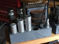
We've polished up the old can capacitors and fitted them back onto the amp chassis. I still need to purchase one more of these, but am having difficulty finding the straight 35mm (1.375") diameter style.
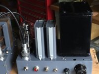
Last weekend we purchased some boards of different timbers to see what is going to look the best for a base, but a decision on this is on hold until we decide what to do about a preamp and what additional real estate will be needed on the board for that.
The old Bakers Selhurst full range driver needs some heavy EQ to sound acceptable, it needs a modicum of bass and treble boost and a deep notch to kill a dreadful tweeter/dust cap resonance, so I've been using a miniDSP between laptop and amp. To some (us included) this is far from ideal so I'm investigating if a more basic bass and treble tone control circuit can be used together with an analogue notch filter.
Thanks again for everyone's input on the rectifier issue. We're getting close to the end now.
And BTW, it is still sounding fantastic! The plan is to hook up a turntable this weekend and play some of my dad's early stereo LPs.
Graham.
My work has been way too busy, so progress this past week has been slow, but we did get bleeder resistors added in the power supply chassis. We had a few 47K 2W resistors left over from the build, so we used two of those in series. This has dropped the B+ a little, but the caps now discharge in a reasonable time after switch-off.
Whilst the power supply was upside down I replaced most of the out-of-place looking zip ties with waxed string - it's a long long time since I've used this method, and it looks appropriate here! We also took the opportunity to add a dropper resistor in series with the indicator globe to bring the brightness down until I can locate a lower power globe.
We've polished up the old can capacitors and fitted them back onto the amp chassis. I still need to purchase one more of these, but am having difficulty finding the straight 35mm (1.375") diameter style.
Last weekend we purchased some boards of different timbers to see what is going to look the best for a base, but a decision on this is on hold until we decide what to do about a preamp and what additional real estate will be needed on the board for that.
The old Bakers Selhurst full range driver needs some heavy EQ to sound acceptable, it needs a modicum of bass and treble boost and a deep notch to kill a dreadful tweeter/dust cap resonance, so I've been using a miniDSP between laptop and amp. To some (us included) this is far from ideal so I'm investigating if a more basic bass and treble tone control circuit can be used together with an analogue notch filter.
Thanks again for everyone's input on the rectifier issue. We're getting close to the end now.
And BTW, it is still sounding fantastic! The plan is to hook up a turntable this weekend and play some of my dad's early stereo LPs.
Graham.
Attachments
bulgin, I'm glad that we've been able to entertain you! I'll pop over and have a look at the Pye progress.
Graham.
Graham.
I am very impressed with your attention to detail🙂
Much applause for 'bring 'em back alive'.
Regards
bulgin/andre
Much applause for 'bring 'em back alive'.
Regards
bulgin/andre
- Status
- Not open for further replies.
- Home
- Amplifiers
- Tubes / Valves
- Williamson amplifier re-build